When you prepare a configuration and save a firmware to HEX, Firmware Configurator stores a brief description of all some outputs in a proprietary Zigbee attribute. This description allows you to properly process and display GPIO outputs and analog values in your high-level system.
Please note, this description does not include information about values that the firmware sends using standard Zigbee clusters where a value format and units are described in the Zigbee specification (e.g., lightingColorCtrl, genLevelCtrl, msTemperatureMeasurement, msRelativeHumidity, msPressureMeasurement, msIlluminanceMeasurement).
If you create a custom converter in Firmware Configurator for your device and add it to your system (e.g., Zigbee2MQTT), you do not need this info because the necessary logic will be implemented in the created converter.
Cluster: GEN_BASIC (ID: 0)
Attribute ID: 32768 (0x8000)
Data type: Char String (ID: 0x42)
String format
One string contains information about all configured endpoints delimited by the “0x0D” character (ASCII CR).
The information of one endpoint is encoded as:
ABCCC[,DDD,[EEE]]
A – the endpoint number encoded as one hexadecimal character (‘1’..’9′, ‘A’..’F’, ’10’).
B – value access rights encoded as one character:
- R – the value can be read and reported.
- W – write only.
- r – report only.
- * – read, write, report.
CCC – value ID. The firmware sends this ID in the “BASIC_DESCRIPTION” attribute with the corresponding analog value. If this value is empty, this endpoint and sensor on that endpoint has a single analog value (ID is not required). The firmware currently has the following standard IDs.
- * – Generic GPIO output (On/Off).
- # – Read only GPIO contact sensor. A subtype of the sensor is defined in DDD.
- A – current.
- V – voltage.
- m – Altitude.
- lx – Illuminance (lux).
- W – Power.
- Wh – Energy.
- Hz – Frequency.
- pf – Power factor.
- ppm – air quality value.
- ERR – error code.
- 1-9 – any other value without a type (e.g., MODBUS data).
DDD – the optional value’s description (e.g., Voltage, Current, Counter).
The types of a contact sensor is defined as a single character:
- c – contact.
- g – gas.
- n – noise detected.
- o – occupancy.
- p – presence.
- m – smoke.
- s – SOS.
- t – tamper.
- v – vibration.
- w – water leak.
EEE – the optional analog value units encoded as a string (e.g., V, A, or lux).
Examples
Please ignore single quotes in these examples. They were added for better reading.
Example 1
Output pins:
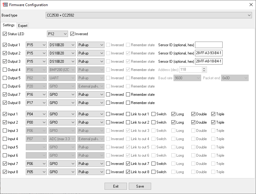
P30: Output 1, GPIO (Role: Generic)
P31: Output 2, GPIO (Role: Contact)
P32: Output 3, GPIO (Role: Water leak)
P33: Output 4, GPIO (Role: SOS)
P02: Output 5, MODBUS RTU (UART: 9600 8N1, Device address: 1, Function: 3 – Holding registers, Memory offset: 0, Data type: Unsigned 16 bit (Big-endian), Number of values: 2)
P37: Output 6, Internal temperature
P35: Output 7, Source voltage
P36: Output 8, Uptime (sec)
Configuration description:
‘1**’0x0D’2R#,c’0x0D’3R#,w’0x0D’4R#,s’0x0D’5r1,Value 1’0x0D’5r2,Value 2’0x0D’7RV,Voltage,V’0x0D’8R,Uptime,s’
Example 2
Output pins:
P30: Output 1, GPIO (Role: Generic)
P31: Output 2, GPIO (Role: Contact)
P32: Output 3, GPIO (Role: Water leak)
P33: Output 4, GPIO (Role: SOS)
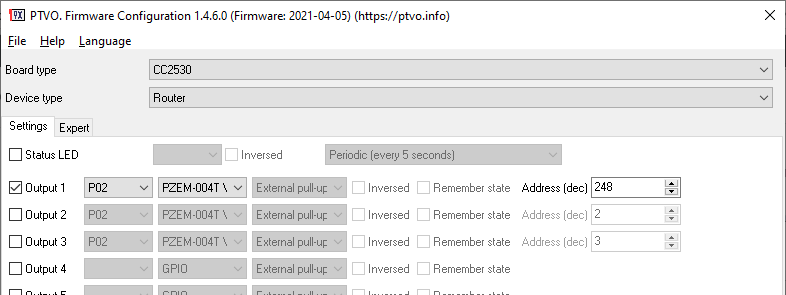
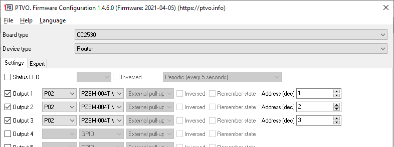
P02: Output 5, PZEM-004T V3 (Address (dec): 248)
P37: Output 6, PZEM-004T V3 (Address (dec): 248)
P35: Output 7, PZEM-004T V3 (Address (dec): 248)
Configuration description:
‘1**’0x0D’2R#,c’0x0D’3R#,w’0x0D’4R#,s’0x0D’5rA,Current,A’0x0D’5rV,Voltage,V’0x0D’5rWh,Energy,Wh’0x0D’5rW,Power,W’0x0D’5rHz,Frequency,Hz’0x0D’5rpf,Power factor’0x0D’6rA,Current,A’0x0D’6rV,Voltage,V’0x0D’6rWh,Energy,Wh’0x0D’6rW,Power,W’0x0D’6rHz,Frequency,Hz’0x0D’6rpf,Power factor’0x0D’7rA,Current,A’0x0D’7rV,Voltage,V’0x0D’7rWh,Energy,Wh’
 Owner
Owner