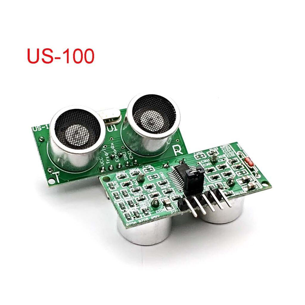
These ultrasonic sonar distance sensors are really common in robotics projects, but they can also be used for automation, interactive art, and motion sensing. They work at about 2 cm to 450 cm away, but we think 10 cm – 250 cm will get you the best results. Sensors look very similar and have a pair of flippers.
⚠️ THIS FEATURE IS NOT AVAILABLE IN THE CC2530/CC2531 ROUTER FIRMWARE
The US-100 is very similar to the popular HC-SR04 ultrasonic sensor and even looks the same, but it can work in the UART mode and provide more precise measurements. Compatible sensors are (there are many clones, but you can find examples of data packets below):
HY-SRF05, HC-SR04, HC-SR04 3-5V, US-100, HC-SR04P, US-015, US-016, HC-SR04+, US-026, IOE-SR05, RCWL-1601, AJ-SR04M:
These sensors return two bytes with a distance values:
0x12 0x34 (MSB LSB)
MSB – most significant byte.
LSB – less significant byte.
HRLV-MaxSonar series:
The sensor returns a value as ASCII characters:
R1234<CR>
<CR> – ASCII code 0x0D
JSN-sr04t, DYP-A01, A02YYUW:
These sensors return two bytes with a distance values:
0xFF MSB LSB CRC
0xFF – fixed header byte.
CRC – Checksum as a sum of all bytes before.
JSN SR04T v2
Same as the sensor above, but CRC = MSB + LSB
DFRobot URM06, URM07:
These sensors return two bytes with a distance values:
0x55 0xAA 0x11 0x02 0x02 MSB LSB CRC
0x55 0xAA – fixed header byte.
CRC – Checksum as a sum of all bytes before.
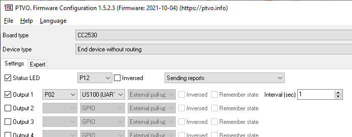
Zigbee firmware configuration for US100
It would be best if you used the jumper is on the board to select the UART mode.

Connections
P02 (UART RX) → Tx
P03 (UART TX) → Rx
GND → GND
3.3V → VCC
Do not forget about the jumper. If you do not receive data from this sensor, try to swap RX and TX wires.
US-100 note: 1. The datasheets for this sensor claims sensor’s current 2 ma. But when the sensor communicates through UART, the current increases to 13-15 ma. Furthermore, I’ve discovered that the UART interface of on the sensor requires 3.3V or higher. Otherwise, it will not return any values.
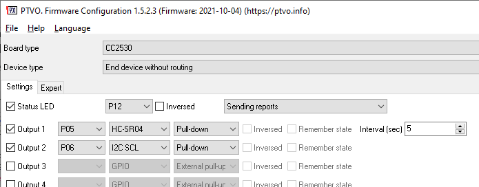
Zigbee firmware configuration for HC-SR04 compatible sensors
This sensor requires a trigger signal to start a measurement, and the firmware uses the “I2C SCL” signal for it. It would be best if you defined it immediately after the HC-SR04 sensor.
Note: the firmware cannot measure a signal width with precision in microseconds. Therefore, the measured distance is rounded to about 15 centimeters. If you need better accuracy, use US100 instead.

Connections
I2C SCL → Trig
HC-SR04 → Echo
GND → GND
3.3V → VCC
Interval
If the value in the “Interval” field is not zero, the firmware executes measurement every N seconds. It sends a new value to a coordinator only if a distance value changes. But the firmware always sends the latest measured value with a periodic report.

Vadym
Can i connect two HC-SR04 ultrasonic sensors to CC2530?
Owner
You can connect only sensor in the UART mode.
Vadym
Where can I read how to do this?
Owner
You can switch the sensor to the UART mode using a jumper on the sensor. The firmware settings are described on this page.
Vadym
But HC-SR04 doesnt have a jamper . Its only on US-100
Owner
I see. Yes, you can add two of these sensors if you have unused pins for each sensor on your board.
Pavel
Hi, there is a version of jsn-sr04t-v3-0, that too has a serial connection, but a little different:
Serial mode operates at 9600 baud and works similar to serial mode on the US-100 module. The main difference is that it also returns a start byte and checksum byte. It also can be operated in an automatic mode of operation where the module is automatically triggered every 100mS.
The way Serial mode works is as follows:
The module is normally idle.
A command bye of 0x55 on the RX pin initiates a detection cycle.
The module responds with 4 bytes of information
Start bye of 0xFF
Most Significant Byte (MSB)
Least Significant Byte (LSB)
Checksum Byte
The returned value can be calculated using the formula (MSB * 256) + LSB.
The checksum byte is calculated using 0xFF + MSB + LSB. It returns the least significant byte of the calculation only.
It seems, that ptvo uses just the first two bytes, that is 255 and MSB and does not read the rest.
Is it possible to make it work with this type of sensor too?
Regrads
Pavel
Owner
Hi,
Please add your request on Github.
Tomas
Could you please tell me how wire and configure JSN-SR04T v3.0 in PTVO gui?
Owner
Does this version have something special? Otherwise, all pins are described on this page.
Igor
Can anyone figure out why it’s not working? I have the same problem, I don’t receive data…
Owner
Please open an issue on Github, describe your configuration and sensor.
Tom83
Hello,
I flash E18-MS1-PCB with PTVO firmware with same configuration for connect HC-SR04.
Status led slow flash when it’s associate with zigbee2mqtt but I don’t receive any distance value.
I check signal with SALEAE on pin P05(18) and pin P06(17) :
– P05 stay at high level.
– P06 stay at low level.
Firmware never send trigger signal.
What I do false ?