 Owner
Owner Owner
OwnerThis sensor type allows you to easily process data from an external MCU like Arduino and send to a coordinator or vice versa. In contrast to the regular UART channel, this sensor does not require additional data processing on the coordinator side.
⚠️ THIS FEATURE IS NOT AVAILABLE IN THE CC2530/CC2531 ROUTER FIRMWARE
How to configure the firmware
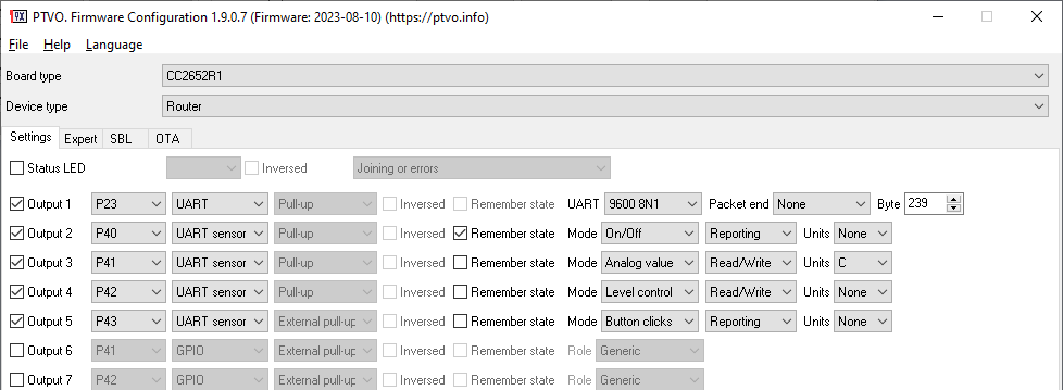
- Firstly, you should configure an UART connection with your MCU (baud rate, parity, and number of stop bits). It should be configured before all UART sensors. This feature is incompatible with other UART-based sensors like MHZ19, Senseair S8 or MODBUS.
- Add one or more UART sensors with the necessary subtype.
The figure above shows an example of four UART sensors.
UART sensor subtypes
On/Off – implements a simple binary sensor with two states: On or Off. It looks like a contact sensor if access rights are “Reportable” or “Read”, and as a switch in other cases.
Analog value – any generic analog value with a single precision float data type (32 bits). Additionally, you can define units for this analog value.
Level control – implements a virtual level control with values from 0 to 255.
Button clicks – allows you to send button clicks (single, double, triple, hold, release) to a coordinator (it always has “reportable” access rights).
Access rights
Reportable – the firmware can send a value to a coordinator. The coordinator cannot request a value or write to it.
Read – reportable + the coordinator can initiate reading of the value at any time.
Write – reportable + the coordinator write a value to the sensor.
Read/Write – all access rights.
UART command format
The firmware supports a special command format optimized for fast data transfer and processing.
You can download the ready-to-use library and examples for Arduino IDE here. Your comments, examples, and improvements are welcome!
<STX><ID><DATA><ETX><CRC>
<STX> – single ASCII character with code 0x21 (!).
<ETX> – single ASCII character with code 0x3B (;).
<ID> – endpoint number and data type encoded in a single byte:
Bits [3:0] – endpoint number minus 1 (0 – 15). It should match the endpoint number in the device configuration. For the figure above, the configuration defines endpoints 2-5 for UART sensors, that should be encoded as 1-4 in a data packet.
Bits [7:4] – data type.
0 – Boolean value encoded as one byte. It can contain 0 (off) or 1 (on) only. Generally, it is used for the “On/Off” sensor.
1 – (UINT8) Unsigned decimal in one byte. Mainly, it is used for the “Level control” or “Button clicks” sensor.
9 – (FLOAT) Single precision value encoded in four bytes (IEEE-754, LSB first). Mainly, it is used for the “Analog value” sensor.
0xE – endpoint command, the command code is encoded as a single byte in <DATA>
0xF – system-wide command.
<DATA> – several data bytes depending on the data type.
<CRC> – checksum for all bytes from <STX> to <ETX>. It is a simple LSB of an arithmetic sum of all bytes. Encoded as a single byte.
Escaping of <STX> and <ETX> bytes in a data packet
It is used to encode and eliminate starting and ending signatures that may appear in <ID> or <DATA> and provide robust data processing.
<STX> – encoded as two bytes 0xDB 0xDC.
<ETX> – 0xDB 0xDD.
0xDB (escape character) is encoded as 0xDB 0xDE.
Note: Checksum is being calculated after escaping bytes.
Commands
1 – the “Get values” endpoint command (firmware > external MCU). The firmware sends it and waits for a response for 500ms before sending a periodic report. The command will be sent for every UART sensor defined in a configuration.
2 – System-wide command (external MCU > firmware) to initiate rejoining process. The firmware sends an echo as an acknowledgement to this command.
3 – “Send periodic reports” system-wide command (external MCU > firmware) to initiate sending of a periodic report for all endpoints.
0xE0 – 0xEF the firmware sends a network status to the external MCU.
0xE0 – Initialized – not started automatically.
0xE1 I- Initialized – not connected to anything.
0xE2 – Discovering PAN’s to join.
0xE3 – Joining a PAN.
0xE4 – Re-joining a PAN in secure mode scanning in current channel, only for end devices.
0xE5 – Joined but not yet authenticated by trust center.
0xE6 – Device joined, authenticated and is an end-device.
0xE7 – Device joined, authenticated and is a router.
0xEA – Device has lost information about its parent.
0xEB – Device is sending a Keep-Alive message to its parent.
0xEC – Device is waiting before trying to rejoin.
0xED – Re-joining a PAN in secure mode scanning in all channels, only for end devices.
0xEE – Re-joining a PAN in Trust center mode scanning in current channel, only for end devices.
0xEF – Re-joining a PAN in Trust center mode scanning in all channels, only for end devices.
Examples
Get value command (from the firmware)
Endpoint #2: <STX> 0xE1 0x01 <ETX> 0x3E
Endpoint #3: <STX> 0xE2 0x01 <ETX> 0x3F
Endpoint #4: <STX> 0xE3 0x01 <ETX> 0x40
Zigbee network status (from the firmware)
Device joined to a network: <STX> 0xF0 0xE6 <ETX> 0x32
System commands (from MCU)
Send periodic reports: <STX> 0xF0 0x02 <ETX> 0x4E
Initiate rejoining process: <STX> 0xF0 0x03 <ETX> 0x4F
Data values (both directions)
Endpoint #3, On state: <STX> 0x12 0x01 <ETX> 0x6F
Endpoint #3, Off state: <STX> 0x12 0x00 <ETX> 0x6E
Endpoint #4, analog value “0.0”: <STX> 0x93 0x00 0x00 0x00 0x00 <ETX> 0xEF
Endpoint #4, analog value “9999.0”: <STX> 0x93 0x00 0x3C 0x1C 0xC6 <ETX> 0x0D
Endpoint #6, single click: <STX> 0x15 0x01 <ETX> 0x72
Endpoint #6, double click: <STX> 0x15 0x02 <ETX> 0x73
Endpoint #6, triple click: <STX> 0x15 0x03 <ETX> 0x74
Endpoint #6, hold <STX> 0x15 0x04 <ETX> 0x75
Endpoint #6, release: <STX> 0x15 0x00 <ETX> 0x71
Data value with escaped bytes
Endpoint #4: level value “219”: <STX> 0x13 0xDB 0xDE <ETX> 0x28
Nico
Why can’t we have UART Sensor with CC253x router firmware?
Owner
There are no free resources for this feature.
Nico
This is not an answer at all. Do you want to tell me, that it only has marketing reasons? Well, then be said, that it will not last long for this project to be forgotten over a ESP32-C6 with Zigbee, which can already be flashed via usb by Arduino with router basis and thousands of libs for FREE. Good luck…
Owner
I mean that there are no free hardware resources for this feature. The flash memory is too small.
Amit
Does your coordinator firmware include UART? And how many max endpoints can be connected to the coordinator
Owner
The coordinator firmware is not configurable. You cannot connect any sensors or external devices to it.
Nirm
If we add and use the UART Sensor, the regular UART channel will no longer be able to send long string/text data from the device to the coordinator, is that right?
Owner
Quick answer: yes, you cannot send raw data. I didn’t try it, but I think, you can try to send raw data from a coordinator to a device.
Nirm
Right, It supports only for sending raw data from the coordinator to a device. Other things, please give us more hex code examples or implementation, for paragraph: Commands 1. Get values… 2.System wide command… 3. Send Periodic reports…
Owner
Thank you for your suggestion. Done.
Nirm
You’ve helped make it clearer for me. Thanks a lot.
Nirm
Could you please explain the functionality of pins P40, P41, P42, and P43 on the UART sensor as depicted in the above GUI image? Additionally, could you confirm if these pins indeed provide actual output?
Owner
These pins are virtual and used for some virtual sensors like UART sensors.
Nirm
Anyway, How many numbers of UART sensors are allowed in this time version?
Owner
You can add up to 8 sensors of any type.