 Owner
Owner Owner
OwnerThe LED edition firmware (FirmwareConfigLED) allows you to create LED controllers with configurable, rich functionality. The firmware can control WS2812B LED strips and other LEDs using PWM outputs.
⚠️ THIS FEATURE REQUIRES THE PREMIUM VERSION
Note #1: The premium version required if your configuration contains 9 and more LEDs in a strip or 2 or more PWMs.
Note #2: You should create an external converter for your device to get full support of all features in your home automation system.
The firmware based on the regular PTVO firmware except for the following:
- The firmware contains a limited set of sensors that are applicable for LED controllers.
- It cannot work as a router and does not support the power saving mode (PSM).
Unique features:
- The firmware allows you to control LED color, even for three PWM outputs, working together (the “LightColor” Zigbee cluster).
- Creating a custom converter for Zigbee2MQTT that supports color control.
- The firmware supports up to 1000 LEDs on CC2652 and 200 LEDs on CC2530. You can split these LEDs into a few strips.
- It can change the brightness of LED strips. Moreover, the firmware can smoothly change the brightness on the selected output.
- You can select from 60 built-in patterns on the selected LED strip: solid color, running light, rainbow, etc. Moreover, the firmware can automatically change the patterns after a specified interval. You can combine this feature with brightness control and create a nice garland.
Hardware limitations
CC2530: You can add LED strips on the following pins: P00 – P03, P10 – P15. If you use P03, the firmware uses the special SPI mode to generate impulses. This method provides a better signal stability, but requires more time to send data for all LEDs. Moreover, you cannot use pins P02, P04, P05 for other purposes because they are assigned to the SPI interface.
CC2652: You can add LED strips on the following pins: P00 – P03, P16 – P21, P25 – P30.
⚠️ WS2812B: if you add a LED strip with more than 100 LEDs, you need an external pull-up resistor for the DATA pin. For example, for 235 LEDs, the resistor is 300 Ohm.
PWM – look here.
Software limitations
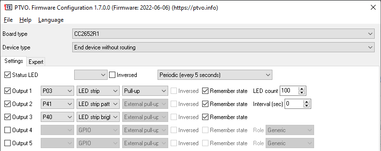
You should define pattern and brightness control channels immediately after the controlled LED strip (see figure above). Both, pattern and brightness control channels are optional.
Color control with PWM outputs
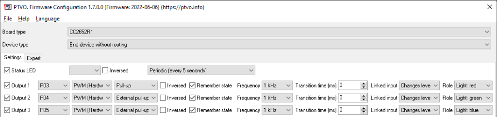
The firmware supports up to five PWM outputs for separate Red, Green, Blue, White and Warm white channels, defined in the RGB order (see figure below and pay your attention to the “Role” parameter). The white channel is optional. When the firmware receives the “LightColor” Zigbee command, it converts X and Y color values to R, G, B levels and sets the corresponding PWM output value.
Please note, the firmware expects the “LightColor” Zigbee command on the “Red” channel only.
You can combine PWM outputs with LED strips.
RGBW – you can add the additional White channel for this controller type. The firmware automatically switches between RGB and W when you select the white color or not.
RGBWW – this controller type has separate cold and warm white LEDs. The “Light: white” channel connects cold white LEDs, and the “Light: White (warm)” channel connects warm white LEDs. The firmware can automatically control both channels when you select a color temperature.
WW+CCT – this controller type contains “Light: white” and “Light: White (warm)” channels only. Here, you can control the brightness and white color temperature.
⚠️ Note: You should always define PWM channels in the following order, without unused outputs and other sensors between: Red, Green, Blue, White, White (warm).
Zigbee2MQTT commands
on/off – Look for commands and examples for GPIO outputs.
Level control of individual PWM channels – Look for commands and examples for PWM outputs.
Color control
Zigbee cluster: ZCL_CLUSTER_ID_LIGHTING_COLOR_CONTROL
Zigbee attributes: ATTRID_COLOR_CONTROL_CURRENT_HUE, ATTRID_COLOR_CONTROL_CURRENT_SATURATION, ATTRID_COLOR_CONTROL_CURRENT_X, ATTRID_COLOR_CONTROL_CURRENT_Y, ATTRID_COLOR_CONTROL_COLOR_MODE, ATTRID_COLOR_CONTROL_OPTIONS, ATTRID_COLOR_CONTROL_COLOR_CAPABILITIES (please look at the Zigbee Cluster Library for data types).
Zigbee commands: read, write.
Topic: zigbee2mqtt/[friedly_name]/set/[channel]
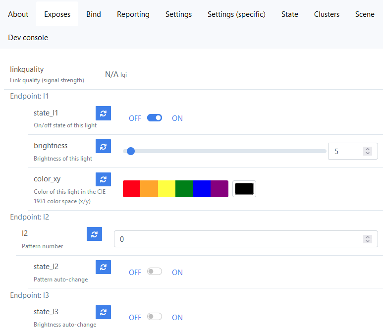
Channel: l1, l2, l3 … l16
Payload: {"color":{"x":value_x,"y":value_y}}
value_x - 0 .. 1 (data type: float).
value_y - 0 .. 1 (data type: float).
example - {"color":{"x":0.49107142857142855,"y":0.42857142857142855}}
Addition LED strip outputs
These outputs extend the basic functionality (brightness and on/off) of a LED strip output. You should define additional outputs immediately after the LED strip output (fig. 1). All these outputs can use virtual pins.
LED strip brightness
When you send the ON command to this output, the firmware starts smoothly changing the brightness of a LED strip as MIN → MAX → MIN. When you send the OFF command, the firmware stops at the last brightness level. Of course, the firmware can remember the last ON/OFF state after power on.
Zigbee2MQTT commands
on/off – Look for commands and examples for GPIO outputs.
LED strip pattern
When you send a numerical value to this output, you can activate a visual pattern or effect on a LED strip. The zero value disables a selected pattern and fills the LEDs strip with a solid color.
When you send the ON command to this output, the firmware starts randomly changing over all available patterns. When you send the OFF command, the firmware stops at the last used pattern or effect.
on/off – Look for commands and examples for GPIO outputs.
Zigbee cluster: ZCL_CLUSTER_ID_GEN_ANALOG_INPUT_BASIC
Zigbee attributes: ATTRID_IOV_BASIC_PRESENT_VALUE (float)
Zigbee commands: read, write

Zigbee2MQTT commands

write - changes the active pattern. This command does not change the ON/OFF state of the LED strip.
Topic: zigbee2mqtt/[friedly_name]/[channel]/set
Channel: l1, l2, l3 … l16
Payload: value (0…60)
LED strip pattern shortcut
When you send the ON command to this output, the firmware immediately switches to the pre-defined pattern. If a LED strip has the OFF state, the firmware switches it on. When you send the OFF command, the firmware restores the previous state. If you sequentially activate several shortcuts, the firmware restores a state before the first called shortcut.
on/off – Look for commands and examples for GPIO outputs.
Zigbee cluster: ZCL_CLUSTER_ID_GEN_ANALOG_INPUT_BASIC
Zigbee attributes: ATTRID_IOV_BASIC_PRESENT_VALUE (float)
Zigbee commands: read, write
Zigbee2MQTT commands
write - sets the pre-defined pattern number. The firmware saves it in NVRAM until hard-reset.
Topic: zigbee2mqtt/[friedly_name]/[channel]/set
Channel: l1, l2, l3 … l16
Payload: value (0…60)
LED strip remote configuration
This output allows you to configure the number of LEDs in a LED strip remotely, for example, if you add a new segment to a LED strip. You must restart your device (power off/on) to apply any change in the configuration. Note: this setting will be reset to a default value after hard-reset or rejoining.
Zigbee cluster: ZCL_CLUSTER_ID_GEN_ANALOG_INPUT_BASIC
Zigbee attributes: ATTRID_IOV_BASIC_PRESENT_VALUE (float)
Zigbee commands: read, write
Zigbee2MQTT commands
write - sets the number of LEDs.
Topic: zigbee2mqtt/[friedly_name]/[channel]/set
Channel: l1, l2, l3 … l16
Payload: value (1…1000, the maximum number depends on the chip type)
Arend
Hello I have bought the premium version of the software to create firmware for a WW/CW led strip. Is that possible using this functions? Because it seems like I need to include a red channel as well to make it appear correctly in zigbee2mqtt.
But when I include a red channel the warm and cold white colors wont work.
What would be the correct approach to make such a device with your firmware?
Owner
Unfortunately, the firmware supports the RGB+WW/CW mode only. I can only offer to control WW and CW channels separately using PWM outputs, or create the full RGB+WW/CW setup. You may use the “gledopto GL-S-007Z.ini” preset as a start point.