 Owner
Owner Owner
OwnerThe power-saving mode (PSM) allows minimizing power consumption up to 0.4 µA in the sleep mode. Of course, attached sensors and peripherals should support power saving too.
Note: I cannot guarantee that the firmware will work correctly in your case because it greatly depends on the schematic of your DIY device. I exhort you to wash your DIY device in an ultrasonic cleaner because a small current leak may consume a battery.
⚠️ THIS FEATURE REQUIRES THE PREMIUM VERSION
Limitations
The power-saving mode has the following limitations:
- GPIO input, the switch mode – the firmware detects ON and OFF states’ changes by a signal rising or falling edge. The CC2530 has a hardware limitation of this implementation. You can add only one switch on pin ranges P00 – P07, P10 – P13, P14 – P17, P20 – P23. Therefore, you can have up to four switches in your configuration. If you define a switch on a pin, you cannot use other pins in the corresponding range for other sensors because it may cause problems with detecting signal edges.
- You may use a board with an amplifier (for example, EBYTE E18, CC2530 + CC2592), but this combination of chips consumes about 180 mA in the active mode instead of 25 mA of CC2530.
- Some sensors are incompatible with PSM (for example, Pulse Generator, SenseAir8, Sensirion SPS30).
- CC253x: The maximum uninterruptible sleep time is about 512 seconds (rounded to 510 s). After this time, the chip wake-ups, updates the sleep times and continues sleep. The device does not poll sensors or activate the radio module at that moment.
Options
The following configuration options may help you to create your battery-powered device:
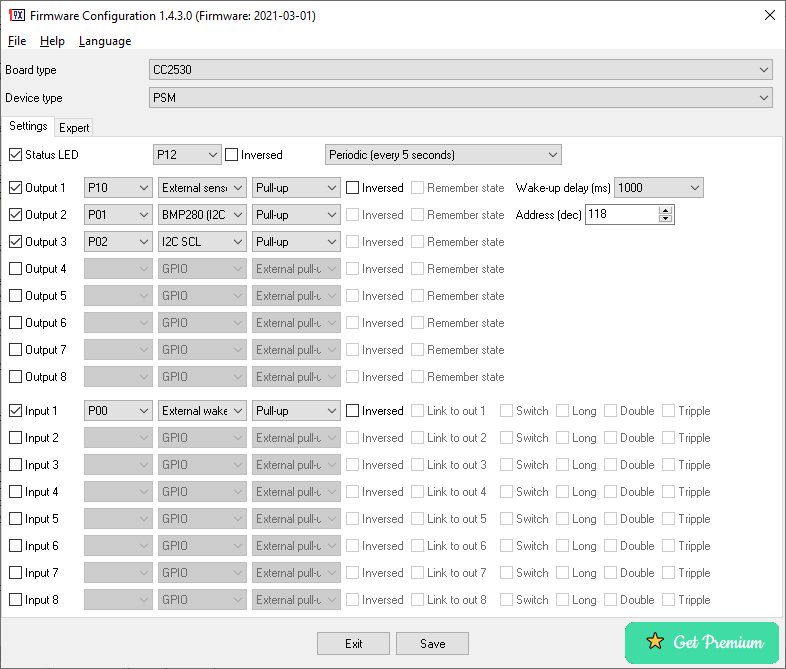
External wake-up – it is a special input type. It wakes up the chip from sleep mode and instructs it to send periodic reports immediately. After this, the chip stays active for 3 seconds and goes to PSM.
If the external wake-up option is selected on Input 1, the firmware also uses it as a system button and allows you to reset the device.
External sensor power control – it is a special output type. The firmware sets the configured output to the HIGH state before reading a sensor’s value, and sets it to LOW after that. The CC2530 and CC2531 chips allow you to use pins P10 and P11 to supply power up to 20 mA to external sensors.
If your sensors require more power, you may use any output connected to an external transistor worked in the switch mode. Please note, the firmware sets all output to the LOW state when it transits to the sleep mode. Therefore, the transistor should be switched off with the LOW control signal.
This output should be defined immediately before a controlled sensor or a group of sensors. Any sensor that does not support external control (GPIO, outputs, switches, internal temperature or voltage, etc.) or GPIO resets the “External sensor power control” setting.
“Wake-up delay” turns on external sensors X ms before reading and sending data so that they have time to warm up, initialize and collect initial data. This value depends on your sensors. It is a maximum value from all sensors controlled by this pin. If “Wake-up delay” is zero, the firmware starts reading sensor data immediately.
Wait for commands after report (on the Expert tab) – The device will wait for 2 seconds after it successfully sent a report with all values to a coordinator. It allows sending some commands back from the coordinator (for example, to configure an interval of periodic reports, control a state of GPIO, etc.).
Poll for queued commands (on the Expert tab) – If you enable this option, the device will wake up every N seconds and send a small request to a parent device (coordinator or router) to check for commands addressed to this device. The device does not poll data sensors and does not send any values to a coordinator. The device consumes rather more power, but you can get a more responsive sleeping device.
LED
The LED indicator works differently in PSM if it is configured.
One short blink per four seconds – the device is connecting to a network.
Sporadic short blinks – the firmware indicates the following actions: clicks, switches, external wake-up signals, periodic reports.
Two short blinks – the firmware cannot send a report to a coordinator.
Pairing
The firmware starts the pairing process immediately after flashing. It tries to connect for about 60 seconds. In case of an unsuccessful attempt, the firmware goes to sleep mode. If you need more time, you should configure the external wake-up input (for example, a button). The signal on that input extends the time for the next 60 seconds.
Re-pairing
Power on, wait 2 seconds, power off, repeat this cycle three times. If the status LED is configured, it should light at a half-bright level for more than 2 seconds while the firmware initializes internal NVRAM memory.
If you selected GPIO or the external wake-up option on Input 1, it acts as a system button. You may click and hold it for 10 seconds. If the status LED is configured, it should light at a half-bright level after 10 seconds.
Recommendations
- Measure the power consumption of an assembled device with a constant power before using it with a battery. You should expect a range of 0.4 – 2 uA for most low-power devices (depending on the schematic and enabled features). If you observe higher current draw, clean your device using isopropanol, a similar alcohol-based liquid, or an ultrasonic cleaner (highly recommended).
- It is important to protect electronic components on your device from impact on the environment (high relative humidity, oxidation of contacts, etc.). I recommend using urethane aerosol spray for it.
- For better power consumption, you should use an external pull-up resistor for all GPIO inputs (3-5 MOhm).
- The firmware measures and sends a battery value with a periodic report. I recommend set to 21600 seconds (6 hours). The periodic report will also help you control the status of your device.
- Some routers work incorrectly with long time sleeping devices. Maybe, you’ll need to change this interval to 300 – 3600 seconds (try various values).
Michael
I use Uart with PSM. A microprocessor wakes it up and sends a couple bytes to the CC2530 Uart.
How much time does the firmware need to receive uart data after sleeping?
What settings are recommended to avoid multiple reports?
Thanks
alain
Hi !
In the PSM mode, how to change the powersource to indicate battery ?
ZB2MQTT use this for the delay “on line” or “off line” (different value if on battery or not)
Thx.
Owner
The firmware sends the battery state with every periodic report. You should enable it, and at least, add one sensor on “Outputs” (e.g., Uptime).
alain
Yes, the voltage state is good.
But the powersource sent by the firmware is on “main” and not “battery” : “powerSource”: “Mains (single phase)”
For example, on my smoke detector (powered by a battery), i have this : “powerSource”: “Battery”.
ZB2MQTT use this value to consider the device up or down and there is 2 values.
By default : 10 min for device on “main” and 1500 min when on battery.
My device have a report every 15 min and as a “main”, is considered as “not seen” between 10 and 15 min.
So, i think the firmware must always send “powerSource”: “Battery” or perhaps add a check box on advanced tab to select beetween “main” and ‘battery” ?
Thanks.
Owner
Probably, you’ve tested the same device with other firmware before. Please try to delete the device in Z2M, stop Z2M, and re-join the device again.
Sebastian
i have problem with PSM mode – I lose readings after about 2-3 hours, disconnecting the power supply and reconnecting it causes it to work again for 2-3 hours. i have CC2530 + CC2591 with BME280 (set default reporting interval to 120s)
Owner
Can you add a wake-up button to your device? If yes, does it help to wake up the device?
Sebastian
sorry my mistake (i have problem with battery) i have another question You wrote “The PTVO can also measure the voltage on a port P03. For this I applied the following configuration:” can i measure voltage of 18650 ~ 3,7 – 4v ?
Owner
No, this chip cannot measure voltage higher than 3.3V.
Sebastian
ok after battery pack replaced it working for about 24h and stop responding. i Try to short the wake-up PIN to GND but without success (the device started reporting again after a power restart.) any ideas?
Owner
This problem can also be related to a router. Can you place your device closely to a coordinator?
Sebastian
I installed a few additional zigbee routers, the signal level is around 30-40, also excellent. But I still lose connection after a few days of work 🙁 what else can I do?
Sebastian
OK small update – when i add routers to my network situation is : device work about 2 weekes and is disconnect from network – power off and on doesnt work. i must delete device from HA and do procedure re-pairing.
Owner
Did try just enable joining in HA? What coordinator do you have? How long is your power off-on interval?
Sebastian
Did try just enable joining in HA?
Do You mean auto join all the time? i think this is disabled by default and when my device dont respond i must use Permit join button and add it again.
What coordinator do you have?
SLZB-06
How long is your power off-on interval?
Could You explain?
Owner
I mean, you can power off your device, leave it offline for 1 week, and try to reconnect after this long time. Or it is 1 second power cut off. I don’t know.
Aramdillo
Nice program. I can program the CC2530 fine and it joins ZHA in Home Assistant ok. The problem is that any sensor measurements (BME280) are only read ONCE at startup with correct data. Other settings (RSSI, binary switches, int. temp) are updating ok but the CC2530 is not updating the other sensors. Any ideas?
Owner
Please submit add issues on Github with screenshots of your configuration.
Vladimir
Hello. I have bought one license to create a PSM device but after flashing the new software it can not even finish the interview in z2m. How can I get some help with this? Maybe I am missing something.
Owner
Add the “External wake-up” button to your device configuration and click periodically while pairing a device.
Vladimir
Hello.
Sorry for my late reply. Didn’t have much time to work on this project.
I have followed your advice and added the “External wake-up” button and kept pressing it while Z2M was trying to interview the device but it still didn’t work.
Is there something else I could try?
Thank you for your help.
Owner
Sorry, but I do not have other ideas.
Pawel
Hi. I have premium version i works fine.
You write “The power-saving mode (PSM) allows minimizing power consumption up to 0.4 µA”. I have 0.4 mA (400µA). I programming the same way like you over comments, even if i cut off sensors
Owner
Please submit your issue on Github https://github.com/ptvoinfo/zigbee-configurable-firmware/issues with your configuration and schematic.
alain
hi !
i’m making some exp with PSM and US-100 on a board with E18-MS1PA1-PCB.
without the US-100, the board use 160uA when sleeping.
with US-100 connected, it’s 2.5mA sleeping, and 11mA in active mode.
i’ve tried to power the US-100 with the power control on P11, but measurement is very erratic.
using wake up delay, no improvment
do you know if other distance sensor work better with power control ?
Owner
Sorry, but the firmware does not support other distance sensors.
alain
Hello,
I suppose that if i need several external wake up pins, i have the same limitation with GPIO switch ?
The external wake up work on High to Low or Low to High signal ?
And could you provide a parameter on the GUI to adjust the awake time (i need approx 15 sec )
Thx.
Owner
Hello,
Yes, the external wake-up pin is similar to GPIO. If you use a pull-up resistor, the active state is Low (transition from high to low), and vice versa. Sorry, but you cannot set the wake-up time to 15 seconds.
Radovan
Hello, I am struggling with PTVO configuration. I have checked several discussions here, it should be possible with PTVO FW without problems – but I am not able to set FW correctly.
1) Input pins P0.0 and P0.1 – in case I set them as input + pullup, the voltage is still 0V. Should be 3,3V (as chip VCC voltage). Tested on several modules, same on all of them.
2) PSM mode – I am not able to pair CC2530 module in HomeAssistant – not working in ZHA nor Z2m. During add new device wizard is end in “Starting Interview”. On the power supply I see the consumption goes to 0mA even pairing is not finished. I have tested to “connect” ~1/second pin defined as external wake-up to GND (configured as pullup) to keep chip awake, but it did not help. Tested several times with several modules, no success. Do you have some solution for this?
3) HomeAssistant can see inputs (switch, switch_2, etc.) only in case the inputs are in PTVO FW config linked to outputs. In other case the input is not visible in HASS. In case in PTVO config I link input to output, I got warning – it is not compatible with PSM mode (it is clear for me, receiver on CC2530 is disabled in deepsleep and I can’t manage outputs). Do you have any solution, how to configure PTVO as PSM mode, where will be used external wake-up for 3 independent sources and visible in HASS as 3 inputs? (as a switch or on/off or something like this)
Generally – I need CC2530 configured as following: 3 inputs, deep sleep. Each of those inputs can wake-up CC2530, send change(s) to ZigBee Coordinator and see those changes in HASS – as I see discussions/articles on this webpages, this should be done quite easily with PTVO FW. I will be glad for some recomended configuration. Thanks for advice.
Owner
Could you please submit an issue on Github where we can discuss these problems in more comfortable format?
Tamás
Hello,
About “External sensor power control”…
Modern sensors (SHT30, SHTC3) are able to complete its power up procedure in about 1 ms, however the firmware config tool allows only 100ms as the lowest value for ‘wake-up delay’ parameter.
– Would it be possible to allow such a low value (1, 5, 10, 20ms) as well?
I am planning to create a temperature sensor with PSM using the reporting interval of 60 seconds, probably lower wake-up delay could help to improve the battery life even more.
Thanks
Owner
You can use a zero delay because the firmware need some time to restore after wake up (about 100ms). So, a shorter interval is not necessary. Moreover, the firmware need 2-5 _seconds_ to go to the sleep mode again. So, the delay of 20ms does not improve the battery life.
Goridat
I am using the PSM mode to run a battery power device. Your firmware configurator works great! I very much appreciate the option to create a custom converter for Z2M. As the project runs on batteries, I need to occasionally measure the battery voltage to get a notification when it is time to replace them. To save on battery, I use a circuit similar as described in https://electronics.stackexchange.com/a/39431 to limit the losses across the voltage divider. Currently, I am manually enabling the control output using a pulse switch. However, the external sensor power control output type sounds like it is exactly what I am looking for. Does it also work with ADC inputs?
Owner
Yes, the external sensor power control output also works with ADC.
Sergey
As I understand it, the premium version is bought for a specific chip. Tied to an ieee address. If my device fails, will it be possible to move the current license to a new chip, deactivating the license from the failed one?
Owner
Sorry, but you cannot move the license between chips.
Сергей
I don’t want to just move. Following the example of Microsoft, when replacing a burned-out motherboard, the Windows license is transferred to new equipment. There are no problems with this.
Owner
There is a large difference in the prices :). Sorry, but you’ll need to purchase a new license. Or you can purchase a bunch of licenses with a discount.
Lantastic
I purchased the premium version of the firmware and I’m experimenting with PSM and CC2652P with a simple schematic to send a report when a switch is turned on AND off but the firmware only detects the rising edge and sends a report only when the logic state is ON and never when is off.
A similar schematic worked fine with CC2530 with PSM.
The same schematic works fine with CC2652P normal firmware no PMS.
Any idea ?
Lantastic
This has been fixed with the latest version.
Both rising and falling edges are now detected correctly and wake up the module.
MK
Hi, I have now “End device without routing” as Device type and pin P00 set as External wake-up, but cc2530 does not go to the sleep mode. Is it necessary to have PSM as Device type, or can I have End device without routing and then wake it up with some pin?
Owner
PSM means ‘power saving mode.’ So, yes, you should select this device type.
Lantastic
I installed the PSM firmware on a CC2530+CC2591 module, no GPIO or sensors, just a input 1 on P00 External Wakeup with pull-up. The device never goes to sleep and keeps flooding the coordinator with continuous reports. I did not manage to make it going to sleep.
Any idea ?
Owner
Hi. What does the device report if it has only the wakeup button?
Lantastic
In this test it had only the wakeup input configured. I just need to monitor a contact on a garage door, so I reflashed the device with an input switch configured and now it seems to work as expected. The device wakes up at every signal edge falling or rising. Will keep the battery consumption monitored.
Owner
Ok. Great! What current do you get now when the device sleeps?
Lantastic
Not easy to measure because when I insert the multimeter in series to the power supply, the device becomes unstable. I managed to measure around 400uA with the contact open. I could not take a measurement with the contact closed.
Olivier
Hello, with premium PSM, is it possible to wakeup every X seconds for example, without using external PIN? Is it also possible to test premium PSM for a day ?
Thanks a lot for this great job.
Olivier
Owner
Hello. Yes, the PSM firmware wakeup if the reporting interval is not zero. Sorry, but you cannot test the PSM version without a license.
Nokia
Hi,
Is there any ZigBee solution for a DIY end device with a low (maybe 1-5 mA?) standby power consumption? I.e. the device is not in deep sleep, and is always ready to immediately receive a command from the coordinator. I know this is possible in commercial products (the Danalock smart lock for example can last many months with 7200mAh total battery capacity), but I would like to achieve similar with a DIY device/firmware. Any suggestions would be appreciated.
Thanks
Owner
Hi,
Does the Danalock smart lock use the CC2530 chip?
Nokia
Hello,
I’m not sure of the chipset used. However, I’ve looked more into this and it seems the POLL_RATE variable is what is being used – when sending a lock or unlock command to the Danalock it isn’t always instant, so it seems to poll for queued commands every few seconds. Can this be done with the deep sleep so that for instance it checks for new commands every 5 seconds? Would this enable 5+ months of battery life?
Thanks
Owner
Hello
There is the “Poll for queued commands” option on the “Expert” tab. It will work in the PSM version too. You can measure consumption and calculate battery lifetime for your case. The average consumption is 30uA in 120 seconds (~21ma per day).
Damian
I have problem with pairing CC2530 in PSM. The same firmware generated but as end device without routing pairs succesfully. But when I set PSM – the it will announce itself, start to interview but interview will fail… I tink that device goes to sleep too fast, and it is not waiting for interview to complete. Next wake up whole procedure starts again – announce, start to interview and after a while interview failed…
Owner
You should add the External wake-up input to your device and configuration. When you pair a device, you should press this button every 30-40 seconds.
Damian
I really don’t want to… External wake-up also sends periodic report, and I need to read counter value each 60 secs, not faster… I could rewrite code to check when last read was done, but I don’t need external wakeup so it is redundant for me.. Could it be fixed in firmware – to not enter into sleep until pairing is done?
Owner
The firmware does not send reports if it is not paired. So, you may press the external wakeup button only when you pair a device and do not touch it other times.