Owner
Owner Owner
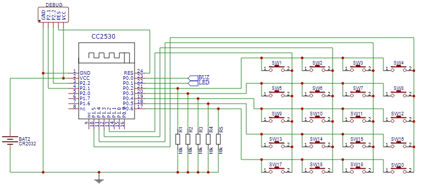
OwnerMatrix keyboards, commonly known as keypads, offer a practical and efficient input method for various electronic devices. Unlike individual GPIO (General Purpose Input/Output) pins used for each key in a traditional setup, a matrix keyboard allows multiple keys to share the same input/output pins through a matrix arrangement. This design provides several advantages over GPIO inputs, including:
- Efficient Use of Pins: By utilizing a matrix layout, a keypad requires fewer pins to accommodate a larger number of keys. This efficiency is particularly beneficial in situations where the number of available GPIO pins is limited. It matters if you need 8 or more buttons in your device.
- Simplified Wiring: With a matrix keyboard, the wiring complexity is reduced as multiple keys are connected in rows and columns. This simplicity eases the assembly process and enhances the overall reliability of the connection.
⚠️ THIS FEATURE REQUIRES THE PREMIUM VERSION
Firmware
I’ve added a custom firmware for the corresponding device type that can also contain other sensors. You can configure it by starting “FirmwareKeypad.exe” in the program folder.
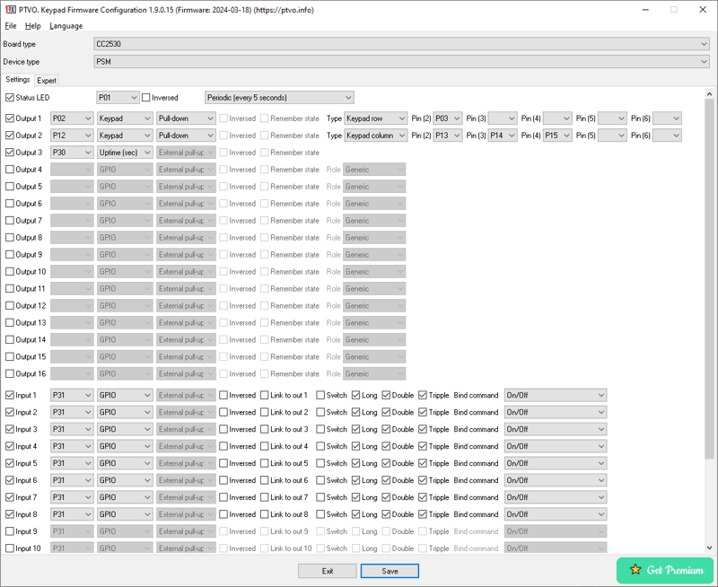
Outputs
Here you should configure your keypad pins. The first defined configuration output (but it can be Output 10, for example) should contain pin definition for keypad rows, followed by the second configuration output that should define pins for columns. The same selected pull mode is used for all pins in rows or columns. Please note, that the external pull-up or pull-down resistor (500kOhm – 3MOhm) can be more power efficient, but you should find the appropriate nominal for your schematic yourself.
Please note, that the firmware supports up to 32 keys. All other keys will be ignored.
Inputs
Here, you define a virtual pin (non-existing pin) for each button on your keypad. For instance, if your keypad has 8 keys (a 2×4 matrix), you define keypad rows as “Output 4” and keypad columns as “Output 5.” Then you should begin defining your buttons starting from “Input 4,” representing “Key 1,” “Input 5” corresponds to “Key 2,” and so on. You can skip some keys in the configuration (undefined input). In this case, the firmware will not report key clicks for it.
If your matrix is too large (for example, 4×6), there are not enough inputs for all keys. In this case, the firmware will only report single clicks for these keys to a coordinator, and you cannot configure modes and direct bindings for these keys.
Note: This dedicated firmware supports up to 16 direct bindings apart to the default firmware with 4 available bindings.
Binding
The “Binding” feature enables the keypad to send a command to a bound device without a coordinator. It can be a simple “On/Off” command for a single click only, but also complex “Dimmer” commands (single click – “Toggle”, double-click – “Off”).
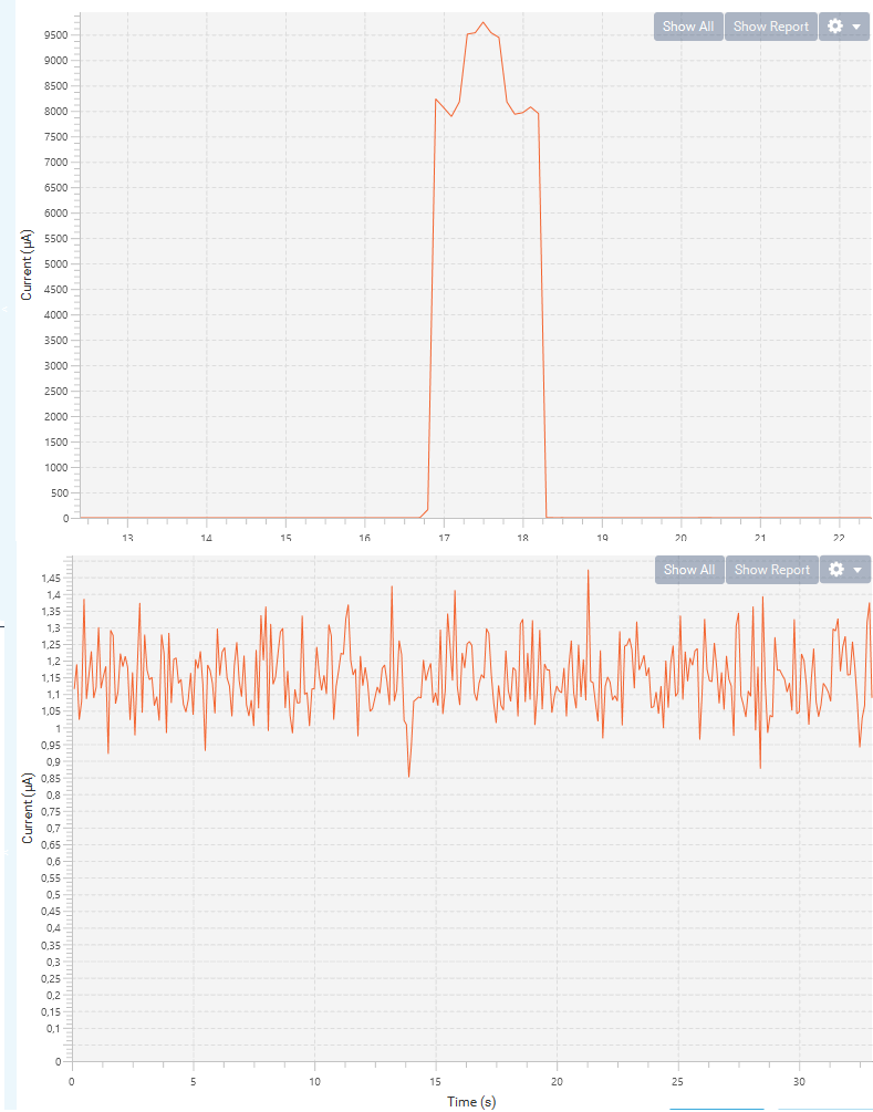
Power efficiency
Certainly, it’s worth noting that the wireless keypad operates without physical connections, and its firmware must prioritize power efficiency to ensure prolonged battery life.
Here are two screenshots for CC2530 for a single key press and sleeping mode.