Owner
Owner Owner
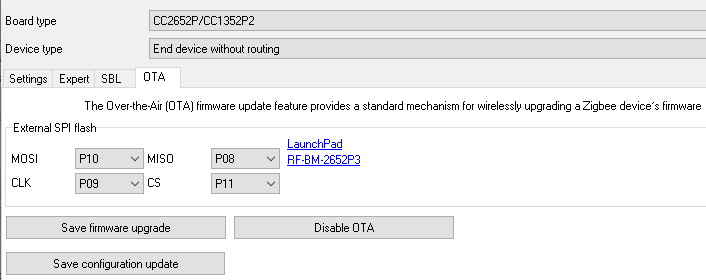
OwnerThe Over-the-Air (OTA) firmware update feature provides a standard mechanism for wirelessly upgrading a Zigbee device’s firmware.
⚠️ THIS FEATURE REQUIRES THE PREMIUM VERSION
⚠️ THIS FEATURE IS AVAILABLE ON CC2652 or CC1352 CHIPS ONLY
Requirements
- CC2652 or CC1352 chip.
- The external flash memory with double the capacity of the internal flash memory size. For example, the CC2652R1 has 384 KB flash. So, the external flash should be at least 768 KB.
- The external flash memory should be one of the following types: Macronics MX25R1635F, MX25R8035F, WinBond W25Q32, W25Q16, W25X20CL, ISSI IS25LP080D (e.g., MX25R8035FZUIL0, Macronics’s SPI 1 MB flash). Look at the LAUNCHXL-CC26X2R1 schematic for the hardware reference design.
⚠️ DO NOT ACTIVATE THIS FEATURE IF YOU DON’T HAVE EXTERNAL FLASH MEMORY.
It may cause unexpected freezes and larger startup time.
How to prepare an OTA compatible device
- Configure the PTVO firmware as usual.
- Configure external flash pins on the OTA tab.
- Save the full firmware using the “Save” button. Internally, the configurator adds a digital signature and bootloader to a full HEX file.
- Upload the prepared HEX file to your device.
- Reset your device using the standard reset procedure. This procedure copies the flashed firmware to the external flash as “Factory default” (you can see fast blinks of the status LED). The factory default image is used in emergency cases, for example if upgrading via OTA was unsuccessful. The device does not accept OTA updates if the factory image is absent or damaged.
- Create a custom converter for your device and add it to Zigbee2MQTT (note, the standard converter for “ptvo.switch” does not support OTA).
How to upload a firmware upgrade via OTA
The firmware’s upgrade overwrites a firmware code and configuration in the internal flash memory. This upgrade may add new features and fix software bugs.
- Configure the PTVO firmware as usual, or load the settings from the existing full HEX file.
- Check or configure external flash pins on the OTA tab.
- Click the “Save firmware upgrade” button on the OTA tab.
- You should get two files with the “*.zigbee” and “*.json” extensions. The first file is the firmware update, and the second file the special index file for Zigbee2MQTT.
- Copy the “*.zigbee” file to the “data/images/ptvo” folder of your Z2M’s installation. If you like, you may change this folder in the index file.
- Add the index file to the Z2M’s configuration (Settings – OTA updates – OTA index override file name). You can omit steps #6 and 7 if you added the same index file before.
- Restart Z2M.
- Switch to the “OTA” tab in the frontend.
- Your device should exist in the list, where you can click the “Check for updates” button and start updating.
- The update process may take about 45–60 minutes. This time depends on several factors: link quality, coordinator performance, number of devices in your network, number of routers between the coordinator and your device.
- After update uploading, the device verifies the image’s checksum and restarts. If the checksum is invalid, the device does not continue, and you should repeat your actions from step #8.
- At this time, a bootloader copies the uploaded firmware from an external to internal flash. The bootloader restores the factory default image if copying fails at this stage.
How to upload a configuration update via OTA
The configuration update does not change a firmware code and cannot fix software bugs. But the new configuration may fully change behavior of your device. If you cardinally change the configuration, you should reset and rejoin it because the coordinator should retrieve and update information about new endpoint and Zigbee clusters.
- Configure the PTVO firmware as usual, or load the settings from the existing full HEX file.
- Click the “Save configuration update” button on the OTA tab. The configuration update file size is small. The update process takes about 3–20 seconds.
- Execute steps #4-12 from the previous paragraph.
Special service commands
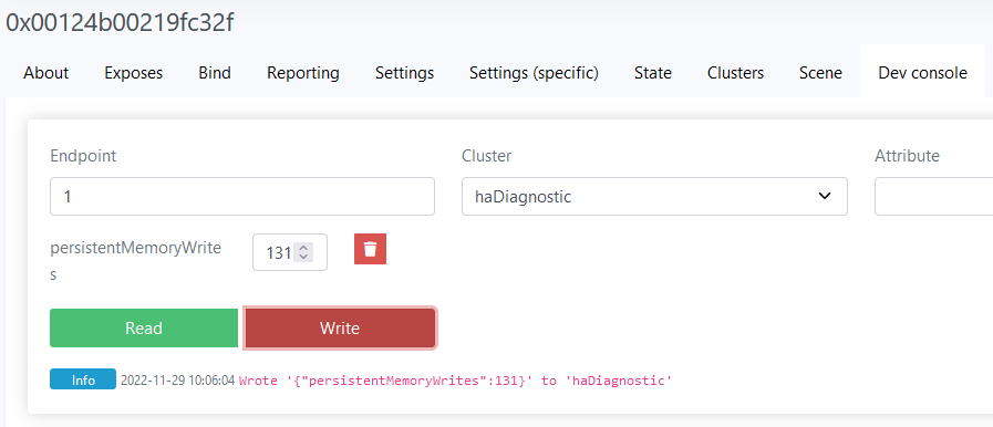
An OTA-enabled device accepts the following service requests via the “write to attribute” Zigbee command. Use this service mode at your own risk!
Commands:
- 129 – Install factory image.
- 130 – Check factory image.
- 131 – Read external flash memory ID. The memory ID contains information about a manufacturer, chip type and capacity. It may help to check compatibility with an installed chip.
- 132 – Fully erase external memory.
- 133 – Perform read-write tests (note: it damages factory default image in the external flash).
- 134 – Lock write operation with the external flash.
- 135 – Unlocks write operations with the external flash.
A device sends a result with help of a standard report that you may see in Z2M’s debug logs. The attribute 16384 (0x4000) contains the result code, and the optional attribute 16385 (0x4001) contains additional data. In the example below, a firmware successfully read an external flash chip’s ID.

Result codes
- 0 – successful operation.
- 1 – unable to initialize the SPI driver (wrong or undefined SPI flash pins).
- 2 – unable to read data.
- 3 – unable to write data.
- 4 – data checksum error.
Zigbee cluster
Endpoint: 1
Zigbee cluster: ZCL_CLUSTER_ID_HA_DIAGNOSTIC (0x0B05)
Zigbee attribute: ATTRID_DIAGNOSTIC_PERSISTENT_MEMORY_WRITES (0x0001)
Data type: UINT16
Zigbee2MQTT
You can send these commands using the web frontend. Go to the device properties – Dev console.