 Owner
Owner Owner
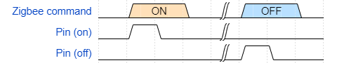
OwnerA latching relay, also called impulse, bistable, keep, or stay relay, or simply latch, maintains either contact position indefinitely without power applied to the coil (wiki). In the electronics world, these relays have two contacts to open and close the switch.
You should define the ON pin first. For example, output 7 – Bistable relay ON, and output 8 – Bistable relay OFF.

Zigbee: Look for commands and examples for GPIO outputs. The firmware accepts all commands on the “Bistable relay On” endpoint.
ahonxxx
After continuous configuration tests, the hardware function is normal in “Routing” mode under the same configuration, but the same error occurs in “End Device without Routing” mode. The level of Yi ‘xia will always be high when powering on, ha control, and the hardware has no report. I hope you can have a look at it. Thank you. Great author
ahonxxx
Board type: CC2652P/CC1352P2
Device type: End device without routing
Model ID: ptvo_zigbee
Update firmware’s timestamp : 2021-08-15
Status LED: P05, Periodic (every 5 seconds)
Set default reporting interval (s): 60
Output pins:
P06: Output 2, Bistable relay On, Pull-down (Impulse (ms): 100, Restore after power off: Last), Remember state
P07: Output 3, Bistable relay Off, Pull-down (Impulse (ms): 100)
P09: Output 4, Bistable relay On, Pull-down (Impulse (ms): 100, Restore after power off: Last), Remember state
P10: Output 5, Bistable relay Off, Pull-down (Impulse (ms): 100)
Input pins:
P26: Input 2, GPIO, Pull-down, Link to out 2
P27: Input 4, GPIO, Pull-down, Link to out 4
ahonxxx
Is the pulse valve in Burmet, Israel controlled in this way? It is positive pulse to open the valve and reverse pulse to close the valve
Owner
Sorry, but I don’t know this valve. The CC2530 chip generates digital pulses (0V – low, 3.3V – high).
ahonxxx
Input pin1 injects high level and out5 high level for 1 second. Input pin1 reinputs high level and out5 high level for 1 second. Cycle. Pin1 is a button switch. Each time it is triggered, the polling output output high level. How much is your email? I will send you the schematic diagram for a detailed
Owner
You need the Pulse switch feature.
ahonxxx
High level 3.3V output for 1s, one switch control, two IO output ports are required for on and off,
http://www.bermad.com.cn/
This is the valve website. I will connect a high-level trigger 12V at the IO output port, and the ZigBee module will output to the high-level for 1 second
ahonxxx
Configuration implemented in esphone
There are too many devices connected to WiFi. I want to change it to ZigBee networking. Thank you
switch:
– platform: gpio
name: “switch1”
pin: GPIO4
on_turn_on:
– output.turn_on: K10
– delay: 1ms
– output.turn_off: K10
on_turn_off:
– output.turn_on: K11
– delay: 1ms
– output.turn_off: K11
output:
– platform: gpio
id: K10
pin:
number: 10
mode: OUTPUT
inverted: false
– platform: gpio
id: K11
pin:
number: 11
mode: OUTPUT
inverted: false
Owner
Ok. The “Bistable relay” implements the same logic.
ahonxxx
I will purchase electronic modules for testing immediately. Thank you very much
ahonxxx
The function can be realized after testing, but the initial state of power-on after power-off is not correct. The defined Bistable relay OFF GPID is always high level. Ideally, it is to remember the last switch state after power-off and then power on (correctly, it is to give a high level of 100 milliseconds once), instead of always high level. So my valve coil keeps burning a little bit, a long time,
gio
Hi, i can’t understand how this bistable feature works: the name shouldn’t be “monostable”? I intended that this output has only one stable position and after impulse time has passed returns to the monostable position (ON or OFF). Isn’t it?
THen, it is possible to command this output by an input?
Can you add a configuration example?