 Owner
Owner Owner
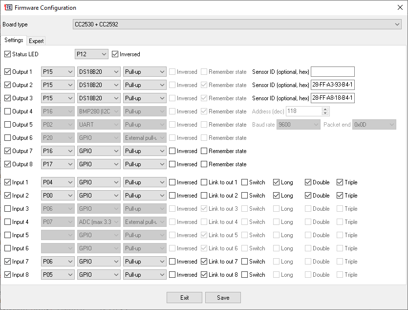
OwnerNo programming language is required for this firmware. You launch a program, select the necessary options in the graphical interface, and click “Save” to get ready to flash a HEX file in seconds.
The list of features became too long, and I’ve split it into several pages.
- Premium version
- Changelog
- General information (LEDs, pairing)
- Expert options
- Power saving mode or battery-powered devices
- Over-the-Air updates (OTA)
- RF signal level control
- GPIO inputs, outputs, and pull-ups
- Analog inputs (ADC), source voltage, an internal temperature
- UART
UART sensor - PWM
- Displays (7-seg, LCD, OLED)
- LED firmware (WS2812B, Color control)
- Flower / Soil moisture sensor
- Keypad (matrix keyboard)
- Pulse generator and counter
- Group switch
- Pulse switch
- Bistable relay / Latching relay
- External sensors
- 1-wire sensors: DHT11, DHT12, DHT22, AM2301.
- DS18B20 (1-wire temperature sensor).
- I2C sensors. General information.
- Environmental sensors (I2C-compatible): BMP280, BME280, SI7021, HTU21D, HDC1080, HDC2080, SHT20, SHT30, SHT35 (select SHT30 in the configurator), SHT40, SHTC3, GXHTC3, TMP102 and others.
- SCD40/41 CO2, temperature and humidity sensor.
- Ambient light (I2C-compatible): BH1750.
- Thermocouple sensors MAX31855, MAX31865 (SPI).
- Air quality sensors: MHZ19, Senseair S8, Sensirion SPS30.
Air quality sensors: PM1006, PMSx003. - TVOC air quality sensors: CCS811, SGP40.
- DC current and voltage monitoring: INA219, INA226, INA3221.
- PZEM-004 V3 AC electricity meter (current, voltage, energy).
- ACS712, ACS758 (AC current meters).
- HLW8032: VAC energy meter.
- MODBUS RTU.
- PCF8583: external counter.
- PCA9685: 16-channel PWM controller.
- Ultrasonic distance sensors HC-SR04, US-100, MaxSonar, URM06, URM07, JSN-SR04T and their clones.
- Digital rotary encoder.
- X9C102, X9C103, X9C104, X9C503 digitally controlled potentiometers.
- HX711 load cell/weight module.
- Real-time clock (RTC, DS3231, DS1307).
- Cron scheduler.
- E18-MS1PA2, E18-MS1PA2-IPX, E18-2G4Z27SI or E18-TBH-28 Test board.
- E72-2g4m20s1e
- Serial bootloader on CC2652 or CC1352. Flashing firmware through a COM port.
- CC2531 configurable router
- DIY examples
Denis
Hey!
I’ve installed your firmware, made an export for z2m, all good, working great.
Can you tell me what is the correct way to setup 1-wire sensor, like DHT11/22? I really searched the internet, there is barely anything for that, the firmware FAQ and manual just mention it as supported and all the options are there. But it’s really confusing, because DHT11/22 is possible setting as for Output pin as for Input. What are those sensors? Are the Input as their 1-wire is kind of data input channel, or are they output?
A small screenshot for 1-wire sensors, even without much description would be really helpful under their support line.
Owner
Hi! You can connect this sensor to Input or Output in my firmware. It does not matter. DS18B20 sensors are more preferable on Outputs because these channels have additional settings.
Denis
Thanks for the reply, I actually tried it both ways, and unfortunately both ways always yield “null” for temperature and humidity, like:
MQTT publish: topic ‘zigbee2mqtt/0x00124b002203c6cd’, payload ‘{“humidity_l5″:null,”l2″:33,”linkquality”:18,”state_l1″:”OFF”,”state_l2″:”OFF”,”state_l3″:”OFF”,”st…
Do you have an idea what/where could I check to figure out the data coming through?
Owner
Sorry, but I don’t have any ideas.
Lantastic
Hello, I created a device handler (quirk) for Home Assistant to natively interface a module with PTVO firmware ad a DHT22 sensor. This can be easily customized for any sensor and allows interfacing to Home Assistant without installing Zigbee2MQTT.
https://github.com/glcos/PTVOquirk
David Baka
Can I use this to drive an IR LED and control an air conditioner?
Owner
No, this firmware does not support IR.
Martin
Hello, thanks for your configurator 🙂 Is there any chance to add support for motion sensor (especially AS312)? Thank you.
Owner
Hello. There are no differences in a used sensor for firmware. Just check voltage levels on an output (3.3V max)
https://ptvo.info/zigbee-configurable-firmware-features/diy-examples/diy-zigbee-motion-detection-sensor-pir/
Giovanni C
Any chance to add support for addressable LEDs?
Owner
Where do you need it? How many LEDs?
Yuri Antunes
Hello there, I’ve been tinkering with an E18-MS1 pendrive style board from ebyte and I’ve seen a lot of people flashing the CC2530 using the method described here: https://zigbee.blakadder.com/flashing_ccloader.html
this method doesn’t require the CCflash from TI, the firmware generated with your program is compatible with this method or should i use the TI flash loader?
another doubt, the telegram group was disabled?
Owner
Hello. Yes, you can flash my firmware using that method. Of course, you should convert HEX to BIN as described there. The Telegram group is active. I saw your post these.
Pavel
Should the device after reflash with new version or after some modification on firmware rejoin into network?
What is the best way to update firmware without to delete and rejoin the device every time?
Owner
Yes, the firmware should start a new joining process. I cannot offer other options.
Etienne
Hi, thx for this great job.
Flash process works fine with a Raspi 4 (CC_erase and CC_write) on a cc2531 with this configuration:
CC2530 w/o oscill; Router; Output1; P15; DS18B20; External Pull-Up.
I see the router on Domoticz but never saw the DS18B20 as a temp sensor even after multiple pairing process (CC2531 is supposed to be distant from Domoticz and supporting temp sensors).
Did I miss something?
Owner
Are you sure that Domoticz supports external sensors?
Etienne
Hi, thx for your quick answer. I will investigate that point.
From your point of view, the configuration is good?
Owner
Please, check that the field with the DS18B20 address is empty. In this case, the firmware will try to detect a sensor.
Etienne
Field empty with router or end point configuration, I’ve got the same trouble, Domoticz doesn’t see the DS18B20. Even worth, with the end point configuration Domoticz doesn’t see any CC2531 device.
I don’t understand but will not give up (for the time being).
What could not be clear for you in my request is that Domoticz already has a coordinator (Zigate) and that I want to add a distant CC2531 with DS18B20.
Etienne
Hi. I’m coming back to the CC2531 pinout, maybe I missed an information.
Could you confirm to me that if I select “Output 1 – P15” in PTVO, the DS18B20 should be connected to the hole #7 (P1.5) of the IO connector?
Thx a lot.
Owner
I suppose you use the standard CC2531 stick. Yes, the Data pin of DS18B20 should be connected to hole #7 (P1.5). GND -> GND, DS18B20 VDD -> ?
Robin
I see no information how to setup clusters that can be used for bindings. For example, if I have a pwm output (or something else that I can use to control a “continuous value”), that I want to control with a remote by binding genLevelCtrl, how would that be configured?
Owner
The firmware automatically uses the genLevelCtrl cluster for PWM outputs. You cannot change this setting in the firmware. You can bind another compatible remote control to this cluster using Zigbee2Mqtt, for example.
Chris
Is it possible to disable reset/unpair when the power is cycled.
This is causing problems of unwanted reset.
Thanks.
Owner
Sorry, but it is not possible. Maybe, I’ll add this option in the future.
Igor
Hello.
in the PSM mode, the counters do not increase – they are equal to 0.
on all ports in the input section
tell, how to fix it?
ver 1.4.3.0
Owner
I’ve checked the counter in the PSM mode. It works. The temperature sensor value will be OK in the next version.
Igor
you can show a screenshot of how to connect the counter correctly in PSM
Owner
I’ve used your configuration.ini file.
denis
Hi,
im trying to flash Modkam 8ch relay module to use with ds1820 temperature sensors.
i used the video provided by AlexKvazis on youtube and set same parameters, but i don’t get any changes in Homeassistant.
I just see switch 1 ( instead of seeing temperature sensor) clicking which doesnt get any effect
Maybe im missing something?
I would like to use my modkam Relay with 8 or more temperature sensors to monitor my heat system in house but im unable to get 1 working
Owner
Hi Denis,
First of all, you should check Zigbee2MQTT receives that value. Then, you should add the corresponding value in HA.
denis
Here is what mqtt has on relay with programmed 1 output as ds1820b sensor with sensor connected
i use externall pull up to that output, input 1 is disabled
{“linkquality”:55,”state_l2″:”ON”,”state_l3″:”ON”,”state_l4″:”ON”,”state_l5″:”ON”,”state_l6″:”OFF”,”state_l7″:”OFF”,”state_l8″:”OFF”}
Owner
It looks like the firmware cannot detect your sensor.
Anton
Hi, does your firmware support rotary encoders? Couldn’t find it in the docs. If not, do you plan to add it?
Owner
No, the firmware does not support rotary encoders.
Drbios
Hi … About the premium version 6+ … How many devices can I flash? …(I am making a lite of diy switch and sensors for my home) I amusing a AliExpress cc2530 module.
Owner
6+ means you can purchase a license for the necessary number of devices.
gio
Hi, i noticed there is a Premium version now. I would like to ask why there is an option that say: “License for another person”. I also have other questions about premium version:
1. If i buy a license and after some time i would give my device to another person, would it be possible? How?
2. What happen if a board where i used a licensed firmware breaks? The license is lost?
Thank you
Owner
1. You can give your device to another person, but you cannot transfer your license to another person. So, that person cannot create and install the PTVO firmware himself without buying a new license.
2. Yes, you’ll lose the license for that device.
Giovanni
Sorry, but point 1. is not completely clear to me: i read that license is linked to cc25xx device, so why it can’t be transferred to another user togheter with the device? You mean that if i give a device (for wich i bought a license) to another person, that license is lost? Or I’m missing something?
Owner
Because if you’ve purchased a license for 5 devices but give only one device, I cannot split it. There are no problems if you purchase a license for one device and give it with that device.
Techno
By any chance is it possible to use gpio expander ? (MCP23017 or PCF8574T)
Owner
I’m sorry, but my firmware does not support any expanders.
Darius
Hi. Is it possible to control multiple outputs from a single input?
Owner
Yes, it is possible using the Group switch mode (https://ptvo.info/zigbee-configurable-firmware-features/group-switch/). Outputs cannot control inputs at all.
Darius
Very nice. What about two or more inputs controlling a single output? I see group switching as a kind of redirection to other outputs but missing a feature to redirect (link) multiple inputs to a single output. For example. 3 wall switches controlling a single lamp.
Owner
Sorry, but it is not possible.
Darius
what would happen if I configured three outputs as group switches to switch a same single output?
Owner
Sorry, but I didn’t understand your configuration. Could you please attach a screenshot?
Darius
here you go https://drive.google.com/file/d/1anDfPw9S3_IbuxtdrJMqYY1AAQIysm2T/view
Owner
In this configuration, inputs 1-4 control output 4.
gio
Hi, i noticed that all GPIO used as output, go at mid 3.3 voltage for a while at boot (remember state disabled; all outputs should be off at boot); after that they all go low. Only GPIO that stay at 0V at boot are GPIO 1.1 and 1.0 (20mA GPIO’s). Is this normal?
Owner
All GPIO are configured as inputs when the chip starts. Therefore voltage depends on your schematics. When the firmware starts, it configures GPIO outputs in the first palce, but a small gap of an unknown state is possible.
Giovanni
Ok, but there is a reason why GPIO 1.0 and 1.1 (electrically connected like the others) are not affected by this behaviour?
I would like to find a way to have at least 1 output that doesn’t have undefined state at boot (to control a door lock). It seems that gpio 10 and 11 satisfy this requirement.. What do you think?
Owner
Sorry, but I don’t have any ideas.
John
Hi all!
If a configure a CC2530 device as End Node, what about the status its power manager?
Shall i expect, it goes to sleeps autonomously?
Bye,
John.
Owner
Hi,
The firmware does not support power saving and does not go to sleep.
Johnrob
Again your firmware is awesome. I have the BME280 sensor running the 1st try with no issues.
I have a question on the BME data;
The units read from the Zigbee message have a ,76 appended to them.
i.e.
C,76
Pa,76
%,76
Is this coming from your firmware or some Zigbee structure?
Thanks
John
Owner
It is the sensor’s address.
dave
can you tell me hou the External sensor power control works P11 alwas stays on my config below
Board type: CC2530
Device type: Router
Status LED: P13 (Inversed), Joining or errors
Default reporting interval (s): 60
Output pins:
P00: Output 1, DS18B20, Pull-up (Sensor ID (optional, hex): 28-A7-AD-66-33-14-01-32)
P00: Output 2, DS18B20, Pull-up (Sensor ID (optional, hex): 28-AA-92-71-1D-13-02-C1)
P00: Output 3, DS18B20, Pull-up (Sensor ID (optional, hex): )
P14: Output 4, GPIO, Pull-down, Remember state
P01: Output 5, Source voltage
P11: Output 6, External sensor power control, Pull-down (Wake-up delay (ms): 500)
Owner
The “External sensor power control” pin should be defined immediately after a sensor or a group of sensors. In your case, you should move it to Output 4.
dave
i have made The chance but no luck stil 3.3V on 1.1
do i need an external pull up or pull down ?
Board type: CC2530
Device type: Router
Status LED: P13 (Inversed), Joining or errors
Default reporting interval (s): 60
Output pins:
P00: Output 1, DS18B20, Pull-up (Sensor ID (optional, hex): 28-A7-AD-66-33-14-01-32)
P00: Output 2, DS18B20, Pull-up (Sensor ID (optional, hex): 28-AA-92-71-1D-13-02-C1)
P11: Output 3, External sensor power control, Pull-down (Wake-up delay (ms): 500)
P02: Output 4, Source voltage
Owner
It depends on your schematics. Usually, you can select “Pullup” and shortly connect the corresponding output to GND when you want to wake a chip up.
johnrob
I have successfully used your firmware to send an ADC voltage to a Hubitat hub. Hubitat uses groovy. I have configured a CC2530 board for ADC input and GPIO input.
If others are interested, my parse code for the ADC input is:
// Parse incoming device messages to generate events
def parse(String description) {
//log.debug ” 24 Parse description= $description”
def name = null
def value = null
Map map = [:]
if (description?.startsWith(“read attr “)) {
def descMap = zigbee.parseDescriptionAsMap(description)
if (descMap.cluster == “000C” && descMap.attrId == “0055”) {
//___Convert Hex Value to Float _____________________________________________
hexValue = descMap.value
valueHexStr = hexValue.toString()
int intBits = Long.valueOf(valueHexStr, 16).intValue();
float floatValue = Float.intBitsToFloat(intBits);
//log.info ” 38 Voltage=${floatValue}”
// __________________________________________________________________________
sendEvent(name: “voltage”, value: floatValue, unit:”V”, isStateChange: true)
}
}
} // — parse —
def parseDescriptionAsMap(description) {
(description – “read attr – “).split(“,”).inject([:]) { map, param ->
def nameAndValue = param.split(“:”)
map += [(nameAndValue[0].trim()):nameAndValue[1].trim()]
}
}
johnrob
As others have said…awesome piece of software.
I’m having trouble understanding the difference between Inputs and outputs.
At least one of the examples has a Output 1 configured for a DS18B20 sensor. I would have thought it would be an input.
Am I missing something?
Owner
The difference between inputs and outputs is important for GPIO. Sensors can be configured on an input or output. But you can define additional parameters for sensors on an output.
Sergey Stegno
Hallo! I’ve configured firmware for working with 4 DS18B20 and device sending report aprox 2 per second. Is it possible to configure frequency of sensor data reports? Configuring reporting frequency in firmware configure doesnt influe. Thank you.
Fabian
Hi,
Thank you for your firmware it’s really nice and I am already using it with a few custom boards.
I see now it can be used with PZEM-004T, can someone explain how this works?
Do I just connect the PZEM TX to P02 and RX to P03 and set P02 as an output with PZEM-004T ? Do I need to define P03 as an input ?
How the data will be reported in Z2M ?
Thank you,
Fabian
Owner
Yes, connect PZEM TX to P02 and RX to P03 and define only P02 in the firmware’s configuration.
Armand
Hello,
Could your firmware be used to control a garage door opener via a relay? It would require activating and deactivating a GPIO for a (configurable?) time interval (e.g. 400 ms). I didn’t see the option.
Owner
Hello. You can use the ‘trigger’ command on the GPIO output.
https://ptvo.info/zigbee-configurable-firmware-features/gpio/
Karthick
for the latest firmware which is downloaded after 7th December, i need to configure a toggle button function, how to achieve this?
Owner
The configuration program has the corresponding option. Did you experience any problems?
Karthick D
yes even when we configure it as a toggle , it works only as a switch mode.
Karthick D
last week exactly on 18th Nov
Karthick
Hi Is there any way to achieve the switch function?
Owner
The firmware allows you to configure the Switch mode for an input.
Karthick
i tried configuring it in switch mode but it works for only ON function, I mean when the LED is turned OFF through app then we press the switch button it turns it ON but it should turn OFF when the button is released that is not happening
Owner
Add the Toggle option.
Karthick
Hi now i can achieve the switch function when use the older version of the configurable software, but it is not working when we generate hex through the latest version of software. Moreover i am looking for your support in a new project for that i am ready to pay, can you give me your email address so that i can send you the details
Karthick
Hi PTVO,
I am trying to implement a switch based ON-OFF using this firmware, i used the configuration as below;
Board type: CC2530 + CC2591
Device type: Router
Power saving mode (PSM): No
Default reporting interval (s): 60
Output pins:
P02: Output 1, GPIO, Pull-up, Remember state
P03: Output 2, GPIO, Pull-up, Remember state
Input pins:
P12: Input 1, GPIO, Pull-up, Switch, Link to out 1
P13: Input 2, GPIO, Pull-up, Switch, Link to out 2
but the switch input works as a toggle, could you please correct me if i am doing anything wrong?
Owner
The settings look good. When did you download the firmware?
Wolfgang
Great piece of software! 🙂
Do you think it‘s possible to add http://fastled.io library or do you already have plans to do so? This would open a whole new world B-)
Owner
I’ve tried WS2812B. A separate firmware is required because these LEDs require a lot of memory. In theory, the firmware can support up to 144 LEDs only. I think it is better to use an Arduino for this task, and use my firmware as a UART-Zigbee bridge.
Doublet
Finally managed to get the extra features of the firm to work in HA. Here is my recent example for the trigger function:
– platform: mqtt
unique_id: test
name: “Test Switch”
state_topic: “zigbee2mqtt/0x00124b00097331f3”
command_topic: “zigbee2mqtt/0x00124b00097331f3/l1/set”
availability_topic: “zigbee2mqtt/bridge/state”
payload_off: “OFF”
payload_on: ‘{“trigger”: 10000}’
value_template: “{{ value_json.state_l1 }}”
optimistic: false
retain: true
Owner
Thank you for sharing!
Bloubul
Do you have to use MQTT or can you use the Zigbee HA integration instead?
Owner
I develop firmware for a Zigbee device. The higher-level system does not matter. You may use any of them. But I cannot consult how to add a device with my firmware to these systems because I use Zigbee2MQTT only.
Antonio
Hello,
maybe I’m doing something wrong but if I change the status of an output (sending the command to ZCL_CLUSTER_ID_GEN_ON_OFF) the device change its state correctly and immediately sends the relative status but the status is always 0 while if I read the status immediately afterwards through a read attributes or if I wait for the report interval the status is correct.
Another problem that i found is that I enable input1 to reset the device and hold down the button until the device restarts and release it after the device has restarted, pairing does not take place.
Can you verify if they are real bugs or i’m doing something wrong please?
Best regards.
Evhen
Hello.
There is a desire to control the SG90 servo. Is it possible to get a control signal directly from the firmware? For example, set two positions and switch between them, and the servo motor changed the angle of rotation.
Thanks!
Owner
I think the Bistable relay logic is similar to your desire. You may try it.
Evhen
Bistable relay mode will not work. The servo is controlled by changing the duty cycle of the PWM. Frequency 50 hertz, pulse length variation between 1000 (0 degrees) and 2000 (180 degrees) microseconds. I tried PWM mode, but the frequency of 1kHz is a lot. Can I lower the frequency? And it is better to immediately determine the upper and lower positions, and be able to switch between them or set the duration through z2m.
Owner
Sorry, but my firmware cannot help then. You need a custom firmware.
Luuk
Hey! Like you project! I was wondering if you could help, ik wold like to make a 0-10v output controle by zigbee. Whate do you think is the best option, i need to gradualy set the voltige.
Hope you can help!
Owner
Hi! You may add a corresponding transitor for the GPIO output or use a relay.
darksun
Is it possible to produce this firmware for CC26X2R1 and CC1352P_2? I’m looking to turn a https://www.tindie.com/products/slaesh/cc2652-zigbee-coordinator-or-openthread-router/ stick into a Zigbee Router rather than a coordinator, I have CCS and IAR workbench and zstack I see the sample switch and sample light examples but not sure how I can implement everything from this great firmware
Owner
Unfortunately, CC26X2R1 and CC1352P_2 are fully different. It is necessary to create a firmware from scratch.
darksun
I can focus on the CC26X2R1 for now, is it possible to take the sample light application and strip out the light parts to leave the router portion so I can repurpose my cc2652 as a routing firmware. I have all the TI dev IDE setup on a Windows VM, with the sample source code data?
kevin
I find somthing if I publish on topic
zigbee2mqtt/0x00124b001d37a935/set
payload
{
“state”: “ON”
}
The output I1 light ON
but how can we do with the other output?
Owner
Hi. There is a mistake or typo. Replace “I1” to “l1”.
lancereau kevin
Hello, thanks for your configurator, it’s really an amazing tool. I use Jeedom and Z2M and i read all the input, but i can’t commands any ouput, i use the last firmware of Z2M maybe is the reason. I test lot of command with MQTT Explorer, as zigbee2mqtt/[FRIENDLY_NAME]/set { “state_I1”: “ON”} and other. maybe i miss something.
I test with alexa amazone and surprise it work with only one output.
You do a super project. Thanks a lot
Owner
Hi. The correct command { “state_l1”: “ON”} or { “state_l2”: “ON”} (the lower case “l” instead of upper case “I”).
Richard
Is it possible to configure so it doesn’t reset & unpair when the power is cycled a few times quickly, leaving only a long press on IN1 as the method to achieve that? I’ve had it where a momentary fault on the power line caused the device to unpair I think due to the turn power on/off 3x to unpair feature.
Owner
Sorry, but you cannot disable it.
Giovanni C
Hello, is there a way to use this firmware to controlo a curtain motor? this motors need to be powered either to close OR to open but NEVER both at same time, this is normally defined as INTERLOCK, it will be great to be able to have such option in this firwmare!!
Owner
Hello, You may use the Bistable relay outputs. It works in the similar way.
ermanue
I can’t see how to make a curtain work with the bistable.
The curtain motor has two wires, which must be activated so that it moves in one direction or another, not an impulse, but continuously as long as you want it to move, so you would need two outputs for two relays, for example outputs 1 and 2, and two linked inputs, configured as a switch, and some option that prevents outputs 1 and 2 from being active simultaneously.
This is what the Interlock option of the double Aqara relays does, preventing the two relays from operating at the same time.
With the bistable, as far as I have been able to prove, I can only activate outputs 1 and 2 alternately, without controlling which one I want to activate, and only one pulse.
Thanks anyway
Paul Kanthak
Hi, there is a typo in the description of “GPIO Outputs” – “zigbee2MQTT commands:
Payload: {“trigger”, 5000} -> the ‘,’ need to be changed to ‘:’ -> Payload: {“trigger”: 5000}
Thanks again for this excellent project!
Owner
Thank you! Fixed.
John
Can you add OUTPUT: True RMS?
I want to use ACS712 for AC current like this:
https://i1.wp.com/modkam.ru/wp-content/uploads/2020/01/Router-ULN-Google-Chrome-2020-01-20-13.46.08.jpg
Owner
Hi, ACS712 exists in the sensors list.
Paul Kanthak
Hi, I’m trying to use the UART interface with an Arduino Nano and have configured ‘Output 2’ of the CC2530 as described in your configuration specification. Unfortunately I can’t get it to work. Using the Zigbee2MQTT with topic “z2m/[friedly_name]/set/action” and payload “Hello paul” lead to the following error message:
Zigbee2MQTT:error 2020-08-19 19:48:33: Publish ‘set’ ‘action’ to ‘test’ failed: ‘Error: Write 0x00124b001efe861e/1 genMultistateValue({“14”:{“value”:”Hello paul”,”type”:66}}, {“timeout”:10000,”disableResponse”:false,”disableDefaultResponse”:true,”direction”:0,”srcEndpoint”:null,”reservedBits”:0,”manufacturerCode”:null,”transactionSequenceNumber”:null}) failed (Status ‘UNSUP_CLUSTER_COMMAND’)’
Zigbee2MQTT:info 2020-08-19 19:48:33: MQTT publish: topic ‘z2m/bridge/log’, payload ‘{“type”:”zigbee_publish_error”,”message”:”Publish ‘set’ ‘action’ to ‘test’ failed: ‘Error: Write 0x00124b001efe861e/1 genMultistateValue({\”14\”:{\”value\”:\”Hello paul\”,\”type\”:66}}, {\”timeout\”:10000,\”disableResponse\”:false,\”disableDefaultResponse\”:true,\”direction\”:0,\”srcEndpoint\”:null,\”reservedBits\”:0,\”manufacturerCode\”:null,\”transactionSequenceNumber\”:null}) failed (Status ‘UNSUP_CLUSTER_COMMAND’)'”,”meta”:{“friendly_name”:”test”}}’
Zigbee2MQTT:info 2020-08-19 19:48:45: MQTT publish: topic ‘z2m/test’, payload ‘{“state_l2″:”OFF”,”linkquality”:115,”state_l1″:”OFF”,”state_l3″:”OFF”,”state_l4″:”OFF”,”state_l5″:”OFF”,”state_l6″:”OFF”}’
To go ahead I need an idea how to solve this problem. Thanks in advance!
Paul Kanthak
OK, serial communication between CC2530 and Arduino is now in place!
I figured out that the CC2530-P02 is the RX pin (INPUT) and P03 the TX pin (OUTPUT). From my understanding it is confusing as your configuration of the UART defines P02 as output.
In addition it was necessary to configure ‘Output 1’ for the UART connection (using Output 2 was not working).
Thanks a lot for your great project. It enables me to move now all my DIY sensors/actors into my Zigbee network.
Paul Kanthak
Hi, I’m using the UART interface with an Arduino to transmit several status to my Home Automation. Unfortunately I’m not able to send a JSON string as it seems that the firmware add a slash before the double quotes to escape these characters:
MQTT publish: topic ‘z2m/sauna’, … ,”action”:”{\”1\”:\”ausgeschaltet\”}”}’
MQTT publish: topic ‘z2m/sauna’, … ,”action”:”{\”2\”:\”offen\”}”}’
MQTT publish: topic ‘z2m/sauna’, … ,”action”:”{\”4\”:\”28\”}”}’
Any chance to change this behaviour???
Owner
Hi. The firmware does not escape anything. I can only add a data packet end to the data sent.
Paul
Hi, i am using your firmware tool to create own Zigbee devices like switches or temp/humidity sensors, all works fine 😉 Now i want to create UART communication between my Teensy 3.2 microcontroller and zigbee2mqtt (via CC2530 router).
My config looks like this:
Settings: https://ibb.co/VBMNqcZ
Expert: https://ibb.co/L6jyS3R
Device is properly (i think) recognizes by zigbee2mqtt but communication with UART does not work. If i send request to topic: zigbee2mqtt/my_device_id/set with payload: ‘{“action”: [2, 0, 0]}’ i see this error: https://ibb.co/rZwkqkh
Also i periodically(about 2-3s) receive this messages from my device: https://ibb.co/DM6fNQp
I connected P02 pin to RX in my microcontroller and PO3 to TX, on serial port there is no receiving any messages. I would be grateful for any help.
Best regards, Paul 🙂
Owner
1. Please, set the “Packet end” option to “None”.
2. Ensure, that you are using the latest version of z2m.
Paul
Thank You for fast reponse 🙂 I set the “Packed end” option to “None” and result is the same: when i try send payload “11” to topic zigbee2mqtt/my_device_id/set/action i receive error. Also i receive random “action” data from cc2530 like previous.
https://ibb.co/b7C7S5N
Any idea what i am doing wrong?
Best regards,
Paul
Owner
Are you using the latest developers version of z2m? Are you using the latest version of the firmware?
Paul
Yes, i am using the latest version of z2m and firmware tool.
Paul
I found a solution, change UART pin to Output 1. It seems that UART does not work correctly on Output 5.
dclobato
First, thank you for the firmware. I have a CC2530+CC2591 devboard and I created a custom version of the firmware with no sensors, and just the LED on P24. After flashing the module, the flash attached to P24 and GND does not blink :-/ The configuration I have here is on https://paste.ubuntu.com/p/QbHPzwp328/
What can I be doing wrong?
Owner
Hmm. Usually, P24 is not available, because an external oscillator is connected to that pin. But I do not have a firmware for CC2530+CC2591 _without_ the oscillator.
dclobato
It worked! Used pin P03
G
I have created a firmware with only the Reporting LED feature enabled – the pinout of CC2531USB is available at https://www.ti.com/lit/ug/swru221a/swru221a.pdf . I tried two different variants, using both P00 and P11 for the reporting channel.
However, after flashing, it seems like the firmware is not booting properly. Sometimes the LED starts blinking, sometimes it doesn’t. Tried resetting the dongle with the “reset” button of the SmartRF40 and by power-cycling it, sometimes it works fine (LED starts blinking immediately), sometimes it starts blinking after an unpredictable amount of time, most of the time it doesn’t start at all.
Tested with multiple sticks, to exclude any hardware problem. Also tested the old router firmware, and it starts blinking every time I reset/power cycle the stick.
Any idea?
Owner
Please, try the firmware for CC2530 without oscillator.
G
That indeed did the trick, thanks!
John
Why bistable relay ON/OFF can’t work for OUTPUT1 and OUTPUT2?
Owner
Please, re-download the firmware. This bug has been fixed.
John
I want to control Nice Gates Motor.
It have inputs for a buttons: OPEN, CLOSE, STOP and State output for a lamp (open = 24V, close = 0V)
Instead of OPEN, CLOSE, STOP buttons I use simple relay + CC2530 gpio, Instead of lamp I use pc817 + CC2530 gpio. OPEN = P16, CLOSE = P13, STOP = P12.
Cause button press is impulse, I config ptvo with bistable relay.
Board type: CC2530 + CC2592
Power saving mode (PSM): No
Status LED: Yes (Inversed)
Default reporting interval (s): 30
Output pins:
P16: Output 3, Bistable relay ON, Pull-up (500, 0)
P13: Output 4, Bistable relay OFF, Pull-up (500)
P12: Output 5, Bistable relay ON, Pull-up (500, 0)
P17: Output 6, Bistable relay OFF, Pull-up (500)
P23: Output 7, GPIO, Pull-up
Input pins:
P04: Input 7, GPIO, Pull-up, Switch, Link to out 7
Trouble: I can’t config 3 bistable ON relay, only 2 is works.
Temp solution is Bistable1 ON = OPEN ( P16), Bistable1 OFF = CLOSE (P13), Bistable2 ON = STOP (P12).
But in rebooting Bistable1 is OFF and CLOSE command running. I dont want it.
Can you tell me how using 3 bistable relay ON in ptvo?
Owner
Hi. I see only two bistable relays in our configuration.
John
z2m works fine
James
Hi,
I have a CC2530 module and baseboard (Waveshare ZB502) that I have flashed with the latest version of the configurable firmware with settings as shown below:
Board type: CC2530
Power saving mode (PSM): No
Status LED: Yes (Inversed)
Output pins:
P14: Output 1, GPIO, Pull-up, Remember state
P04: Output 2, GPIO, Pull-up, Remember state
P11: Output 3, GPIO, Pull-up, Remember state
P12: Output 4, DS18B20, Pull-up (AA-BB-CC-DD-EE-FF-01-02)
Input pins:
P01: Input 1, GPIO, Pull-up, Switch, Link to out 1
P20: Input 2, GPIO, Pull-up, Switch, Link to out 2
There are two buttons connected to pins P0_1 and P2_0, two LEDs connected to pins P1_1 and P1_4, and a DS18B20 connected to pin P1_2. The board is connected to my zigbee2mqtt network and I am using MQTT Exporer to monitor the network and publish to devices.
when I press a button (P2_0) on the ZB502 board I get the following response:
ZB502_01 = {“state_bottom_left”:”OFF”,”linkquality”:126,”state_bottom_right”:”ON”,”state_top_left”:”OFF”,”state_undefined”:”ON”}
(Where ZB502_01 is the zigbee2mqtt friendly name.)
However, I am unable to publish to the device to get or set the state of the LEDs or buttons. I am using the following to try and set/get pin states:
zigbee2mqtt/ZB502_01/l1/set # turn a LED on
zigbee2mqtt/ZB502_01/l3/set/state:ON # turn a LED on
zigbee2mqtt/ZB502_01/l3/set/state:OFF # turn a LED off
zigbee2mqtt/ZB502_01/l1/get # read the state of button on l1
zigbee2mqtt/ZB502_01/l4/get # read the temperature form the DS18B20
None of these work. I have also tried sending commands from Node-Red but again, nothing seems to work. It appears the the CC2530 can transmit data but is not receiving commands. I am not sure if the is a hardware problem or if I am missing something in the configuration or MQTT publishing strings.
Any help or advice would be appreciated.
Owner
Hi. You use the old versoin of Z2M. In your case you should change l1->bottom_left, l3->bottom_right.
John
I flashed cc2530 + bmp280, try to use it in hassio.
Its cluster data error.
For ZHA no objects created with sensjrs data.
For Zigbee2Mqtt I see objects with any different data.
sensor.0x00124b001d38d3c6_linkquality
l6: 29.93
device: ’77’
temperature: 29.9
linkquality: 0
pressure: 99633
altitude: 141.8
humidity: 56.1
unit_of_measurement: lqi
friendly_name: ptvo_bmp280_linkquality
icon: ‘mdi:signal’
Can you fix Cluster arrays for bmp280?
Owner
Hi John,
Clusters are correct if you see data in Z2M. You should add sensors in HA manually because it is not possible to create it for all possible configurations.
Look here for examples: https://www.zigbee2mqtt.io/devices/ptvo.switch.html
Max
Hi,
John has not tell clear about the problem. I clarify.
There are one inconvenience and one bug.
Inconvenience – all data reported in AnalogInput cluster – temperature, pressure etc, but in ZCL we have separate clusters for each values. So, some software not expect, for example, the temperature value inside AnalogInput cluster, but expect it in temperature cluster.
Bug – when the sensor, connected to the some output, printed not one value (for example, BMP280 has 3 values – temperaure, humidity and pressure), the data transmited to coordinator under the same endpoint and cluster id. It is not possible in that situation to differenciate the values. The only difference – it is “description”, what makes it almost impossible to use that values in almost all software, which not do, of course, the synaxis analize of “description” attribute.
Owner
1. Unfortunately, I cannot implement a separate cluster for each the value type. It requires a lot of memory.
2. See #2. Also, I did it for identical sensors on the same endpoint (DS18B20). Zigbee2MQTT can successfully parse this data.
Alan
Hi. Could you please clarify under the section GPIO Outputs / Zigbee2MQTT commands what would be the channel number of Output 1 with the configuration shown here: https://www.dropbox.com/s/qq1edgmqzifd0qz/ptvo%20configuration.jpg?dl=0
At the moment l1 is the Input 1 Counter and l2 is Input Temperature.
Also, Input 1 Counter is linked to Output 1. Does linking work for Counters? At the moment an LED on Output 1 is always ON but the Input 1 is low (OFF). [Output 1 Inverse is not selected].
Thank you
Alan
Owner
Hi Alan. The LED state may depend on your electronics. It may inverse the signal state.
Alan
Hi. I have simplified the circuit and made some more tests. I removed the Link from the Counter input to the LED output and made a new push button input with a link to the LED. So now I have:
– Input 1(P0.3) Red Push Button 3.3v is config as Counter internal Pull-down (20k)
– Input 2 (P0.2) is config as Internal Temperature – no external hardware
– Input 3 (P0.4) Yellow Push Button 3.3v is config as GPIO internal Pull-down (20k) Inversed & Link to Output 3
– Output 3 (P1.6) Red LED to Ground is config as GPIO internal Pull-down (20k) & Remember State
Circuit diagram here: https://www.dropbox.com/s/xg2uus5my7cb4mv/CC2530%20Testing%20Circuit%20v3.jpg?dl=0
Firmware config screen here: https://www.dropbox.com/s/3gq5nbxa76cjseo/ptvo%20configuration%20V3%20with%2010mins%20and%20Input%202.jpg?dl=0
The firmware is set to report every 10 minutes.
Testing:
1. Input 1 Counter. Pressing push button increments counter as shown in the regular 10 min. reporting.
But publishing message zigbee2mqtt/Solar S0 Counter/get/l1 + payload 1 FAILS with no converter available for ‘ptvo.switch’ with cluster ‘genAnalogInput’ and type ‘raw’ and data ‘{“type”:”Buffer”,”data”:[24,42,1,85,0,0,57,0,0,64,64,28,0,0,66]}’
Devices.js for ptvo.switch here: https://www.dropbox.com/s/yt60eip4oasintt/Devices%20js%20definition%20for%20the%20ptvo%20switch%20re%20S0%20Counter.txt?dl=0
Also resetting counter with ‘zigbee2mqtt/Solar S0 Counter/set/l1 ‘ with data ‘0’
FAILS with error No converter available for ‘l1 ‘ (0)
2. Input 2 Temperature with message zigbee2mqtt/Solar S0 Counter/get/l2 + payload 1 receives message with temperature OK: {“state_bottom_left”:”OFF”,”linkquality”:105, “state_bottom_right”:”OFF”,”l1″:6,”l2″:28,”temperature”:28,”state_top_left”:”OFF”,”l3″:32,”last_seen”:”2020-07-10T22:25:35.794Z”}
3. Input 3 Pressing push button makes the LED come on when the button is released BUT it stays ON. Pressing push button again makes the LED go off when the button is released. Looks like the GPIO is behaving as a Latch not a momentary make/break circuit.
Publishing zigbee2mqtt/Solar S0 Counter/get/l3 + payload 1 to get the push button state is OK: state is ON or OFF as shown by the LED.
In summary.:
1. Counter: Cannot read(get) or write(set) counter – errors “no converter available”
2. GPIO push button input is acting as a latch switch
Hope this helps. Many thanks.
Alan
Owner
Hi,
2. It seems you use an old version of z2m. It does not have the corresponding converter.
3. Enable the ‘switch’ option and it will work as expected.
Alan
Hi. I’m running zigbee2mqtt under docker. I installed the latest image 1.14.1 dated 2020-06-30 16:45:15. I still get the same error: “No converter available for ‘ptvo.switch'”. Here is a copy of the ptvo.switch entry in the devices.js file https://www.dropbox.com/s/hmsw8uxozmf764o/ptvo_switch_1_14_1.txt?dl=0 + the fromZigbee.js file https://www.dropbox.com/s/s1w4azpfusnbp11/ptvo_fromZigbee_1_14_1.txt?dl=0 + the toZigbee,js file https://www.dropbox.com/s/csysdqn1u7lkyni/ptvo_toZigbee_1_14_1.txt?dl=0
Whilst this is all new to me, I see in the zigbee2mqtt log the response is:
type ‘raw’, cluster ‘genAnalogInput’, data ‘{“type”:”Buffer”,”data”:[24,12,1,85,0 ……….
whereas I was expecting to see something like:
type ‘readResponse’, cluster ‘genAnalogInput’, data ‘{“presentValue”:123, “description”:”Counter”}’
Maybe I need a new version of the firmware? I’m on cc2530_io_1.2.2a.44539_firmware
Thanks,
Alan
Alan
Hi. I would appreciate if you have any further thoughts on getting the Counter function working. Thank you. Alan
Owner
Hi Alan. I’ve tested the counter and it works.
Andreas
CNX Software blog post mentioning your Zigbee FW tool https://www.cnx-software.com/2020/05/25/zigbee-firmware-news-ti-z-stack-3-0-zigbee-for-cc2530-ptvo-zigbee-fw-configuration-tool/