 Owner
OwnerThe firmware allows creating a device with easily configurable functionality, including inputs, outputs, ADC, pulse counter/generator, I2C, external sensors.
Features overview
I’ve placed all features on a separate page. It is too long.
- The status LED indicator works now.
- The firmware supports up to 8 GPIO inputs or outputs.
- The “switch” mode for inputs.
- Pull-up and Pull-down options for inputs and outputs.
- Analog inputs.
- Internal temperature measurement.
- Source voltage measurement.
- UART (only text commands between an external device and a host, look at README.txt).
- Simple MODBUS master implementation (reading sensors).
- Some environmental sensors (DS18B20, BMP280, BME280, DHT 11, DHT 22, DHT 12, AM2301, Sonoff SI7021, MHZ19, SenseAir S8, Sensirion SPS30, SI7021 (I2C), CCS811).
- BH1750 (Ambient Light Sensor).
- PZEM-004T (Energy Monitor Sensor)INA219 (DC Voltage/Current Sensor), INA3221 (3-channel DC Voltage/Current Sensor), ACS712, ACS758 (Current Sensors)
- Pulse generator.
- Pulse counter (infinite, resettable, interval).
- PWM (hardware, up to 128 kHz).
- PWM (software, up to 3 kHz).
- Bi-stable relay.
- Watchdog timer.
- Configurable default reporting interval.
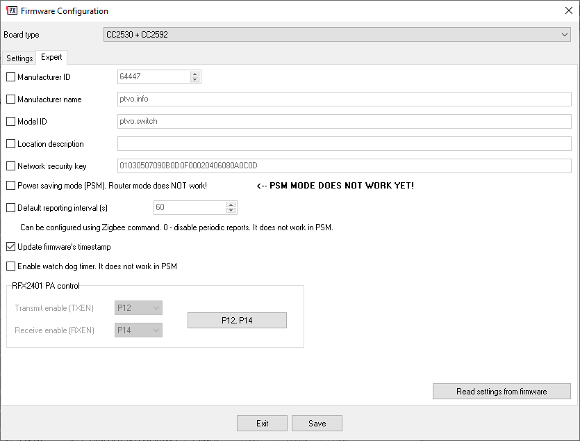
- Expert options (model ID, manufacturer info, network key, etc.).
Download
Your comments and bug reports are welcome :-)!
Changelog
The detailed changelog is placed on a separate page.
 Owner
Owner
Antonio
Hello,
did you check if the status send after change an output via command is correct? Always reported 0 in my test but if i read the attributes or wait for the device report the status is correct. Let me know please if is a bug.
When i hold the reset button if i don’t release it the device restart but doesn’t pair with the coordinator. To pair i must reset the device end release the button befor it starts.
It’s a bug?
Your firmware support OTA Update?
Best regards.
Owner
1. Are you sure that the device sends a state after your command? It is not programmed in the firmware.
2. Yes, of course, you should release the reset button.
3. The firmware is too large, the OTA feature is not possible.
Antonio
Yes i’m sure look :
i read the Zigbee cluster: ZCL_CLUSTER_ID_GEN_ON_OFF Zigbee attribute: ATTRID_ON_OFF and this is the result (the endpoint 2 is off so this is the starting status)
[ZB msg] len: 28 cmd0: 44 cmd1: 81 data: 0 0 6 0 BE B9 2 1 0 60 0 92 B3 7 0 0 8 18 5 1 0 0 0 10 0 BE B9 1D
zigbee_cmd : 0x4481
AF_INCOMING_MSG
group_id: 0
cluster_id: 6
src_addr: B9BE
src_endpoint: 2
dst_endpoint: 1
was_broadcast: 0
link_quality: 60
security_use: 0
time_stamp: 7B392
trans_seq_num: 0
len: 8
data: 18 5 1 0 0 0 10 0
cluster_id : 6
ZCL_CLUSTER_ID_GEN_ON_OFF
0
now i toggle it sending 0x02 to ZCL_CLUSTER_ID_GEN_ON_OFF endoint 2 (the lamp is on) and the device send the status immediately and is this :
[ZB msg] len: 25 cmd0: 44 cmd1: 81 data: 0 0 6 0 BE B9 2 1 0 60 0 A2 A2 A 0 0 5 18 6 B 2 0 BE B9 1D
zigbee_cmd : 0x4481
AF_INCOMING_MSG
group_id: 0
cluster_id: 6
src_addr: B9BE
src_endpoint: 2
dst_endpoint: 1
was_broadcast: 0
link_quality: 60
security_use: 0
time_stamp: AA2A2
trans_seq_num: 0
len: 5
data: 18 6 B 2 0
cluster_id : 6
ZCL_CLUSTER_ID_GEN_ON_OFF
0
but if i read the attribute ATTRID_ON_OFF the result is this (that is correct becaus is ON)
[ZB msg] len: 28 cmd0: 44 cmd1: 81 data: 0 0 6 0 BE B9 2 1 0 60 0 71 26 E 0 0 8 18 7 1 0 0 0 10 1 BE B9 1D
zigbee_cmd : 0x4481
AF_INCOMING_MSG
group_id: 0
cluster_id: 6
src_addr: B9BE
src_endpoint: 2
dst_endpoint: 1
was_broadcast: 0
link_quality: 60
security_use: 0
time_stamp: E2671
trans_seq_num: 0
len: 8
data: 18 7 1 0 0 0 10 1
cluster_id : 6
ZCL_CLUSTER_ID_GEN_ON_OFF
1
If i push the button linked to the output, the device send immediately the status but is always correct (0 if is off and 1 if is on).
About the reset, the problem is when i must release the button because i can’t count 10 seconds 🙂 a need a visual information i don’t know blink rapidly the led so i know that the the device is resetting
Owner
I’ve tested this command and I cannot repeat your problem. I’m using Zigbee2MQTT. Maybe, you could show me your device configuration.
Antonio
Hello, when the router join to a coordinator network i see the ZDO_END_DEVICE_ANNCE_IND message but i don’t see the ZCL_CLUSTER_ID_GEN_BASIC cluster 0x0000.
How can i get the informations about the device like manufacturer ID, manufacturer name etc etc that i set in the expert tab?
Thank you in advance for your answer.
Owner
Hello Antonio. The device does not send this info automatically. A coordinator should request it.
Antonio
Hello, i’m using this function to get the basic cluster ox0000 infornation :
uint8_t st_buffer[3] = { /* Frame control */ 0x00, // Command is global
/* Transaction Sequence Number */0x00, /* control_switch_cmd_seq++ */
/* Value Control */ 0x0000 /* command identifier read attribute */
};
st_buffer[1] = control_switch_cmd_seq++;
af_data_request_t st_af_data_request;
st_af_data_request.cluster_id = 0x00;
st_af_data_request.dst_address = new_switch_address;
st_af_data_request.dst_endpoint = 0x01;
st_af_data_request.src_endpoint = 0x01;
st_af_data_request.trans_id = 0x00;
st_af_data_request.options = 0x10;
st_af_data_request.radius = 0x0F;
st_af_data_request.len = sizeof(st_buffer);
st_af_data_request.data = st_buffer;
zigbee_network.send_af_data_req(st_af_data_request);
}
but i can’t get the informations that i set in the expert tab.
I would to get manufacturerid, manufacturer name and model name but return only 3 bytes.
Can you help me to understand what i’m doing wrong please?
Thank you in advance for you help.
Best regards,
Antonio.
Owner
I’m sorry, but it is out of my knowledge. I can say that Zigbee2MQTT can successfully read all basic information.
Alexey
Hello.
Can you add support for CC2538 modules?
Owner
Hello, No I cannot do it. It is a different chip.
Antonio
Hello,
i am trying to configure a switch.
I don’t understand this:
If you’ve configured the first input pin, click and hold it for 10 seconds.
How should I configure the first pin? I prefer to hold down a button to pair the device.
input 1 P00 GPIO and other parameters?
Thanks in advance for your reply.
Best regards.
Owner
Hello, This feature will be disabled automatically, if you configure the first input as a switch.
Antonio
Hello,
So how i must configure Input 1 ih the gui of your program to start join when i long press the button connected to the pin that i indicate in the input 1 configuration ?
Now i checked Input 1 P00 GPIO External pull down (because i use a touch button that is active high).
It’s enought? or i must configure other parameters of Input 1 in the gui of your program?
Best regards.
Antonio.
Owner
If you want to use this feature you should configure a separate click button on Input #1 and configure your switch on Input #2.
Antonio Poliseno
Ok thank ypu it functions very well.
I’m a beginner of zigbee… but i don’t see the manufacture name and model id that i set in the ui.
Can you help me to get it?
I see the message AF_INCOMING_MSG on cluster_id 12 when i push a button but i don’t see the cluster_id 0 where i think i can get the name and model.
Thank you in advance.
Best regards.
Victor Svetogor
Does anybody know if this board E18-2G4Z27SI will work with the firmware?
According product information http://www.ebyte.com/en/product-view-news.aspx?id=522
there is CC2530, but amplifier chip model unknown.
Owner
Hi. The firmware for cc2530+cc2591 should work on this chip.
Antonio
Hello, congratulations for the excellent and interesting work. I’m new to zigbee programming. Can you share the source code? I’d like to study it to learn more and maybe add other features.
Maui
I really like your firmware, so first, thanks for that.
Do you have any concrete plans on energy saving mode?
I really like the idea of battery powered devices.
PS: sorry for double posting
Alex
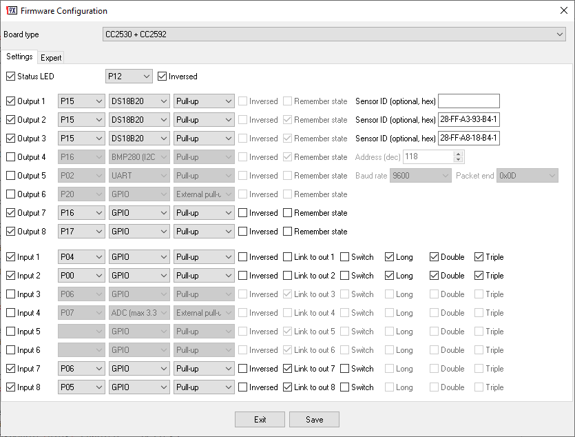
Hi! I’ve tried several variations, but even with a minimalistic configuration (see below) my E18-MS1-PCB does not bind to my zigbee2mqtt server. The status LED just keeps on blinking. Several re-enterings of the pairing mode and re-flashings didn’t help. What am I doing wrong?
Board type: CC2530 + CC2592
Manufacturer ID: 64447
Manufacturer name: ptvo.info
Model ID: ptvo.switch
Power saving mode (PSM): No
Status LED: Yes
Input pins:
P01: Input 1, GPIO, Pull-up
Owner
Hi. Please, try the firmware for CC2530 without a power amplifier. E18-MS1PA1-PCB or E18-MS1PA2-PCB is the board with a power amplifier.
Alex
Thanks. Unfortunately it still doesn’t pair. I flashed my E18-MS1-PCB with this configuration:
Board type: CC2530
Manufacturer ID: 64447
Manufacturer name: ptvo.info
Model ID: ptvo.switch
Power saving mode (PSM): No
Status LED: Yes
Input pins:
P01: Input 1, GPIO, Pull-up
I placed it quite near to my CC2531 USB dongle (with zStack12 firmware v0.26, rev. 20190608).
zigbee2mqtt is version 1.8.0-dev – current version is 1.15 – could that be a reason?
Owner
Sorry, but I don’t have any ideas. How many devices did you connect already?
Alex
I have 5 devices paired – that should not be too many I suppose. But I just tried to pair a Tradfri switch (I already have one paired) and that didn’t work either. So it might rather be an issue with my zigbee2mqtt server. I’ll check it and come back 😉
Alex
…you won’t believe it – the solution was too simple. I found it in the z2m FAQs:
“Stop Zigbee2MQTT, unplug the coordinator, wait 10 seconds, plug the coordinator, start Zigbee2MQTT and try to pair the device again. If none of the above helps, try to reflash the coordinator (does not require repairing of already paired devices).”
After stopping z2m, un/re-plugging the coordinator, and starting z2m again my E18-MS1-PCB with your firmware immediately paired 🙂
Tim
Does your firmware allows direct binding one of the relay with an external remote ?
And vice versa: binding one of the input with a light
(as in : https://www.zigbee2mqtt.io/information/binding.html)
Owner
My firmware accepts bindings. I didn’t try to bind my devices to other devices.
Jens Riebold
Hi, I just completed a nice PCB with the CC2530.
The Output Channels (3) and the Switch are working without Problems.
But I cannot get the temperature, humidity and pressure from the BME280.
I tried all your examples and I updated zigbee2mqtt – nothing helps….
I would expect something like
{ temperature: 22.5, humidity:50.4. pressure=980 }
mosquitto_pub -h localhost -t zigbee2mqtt/ptvo1/l3/get/l3 -m “”
also
mosquitto_pub -h localhost -t zigbee2mqtt/ptvo1/get/l3 -m “”
Received Zigbee message from ‘ptvo1’, type ‘readResponse’, cluster ‘genAnalogInput’, data ‘{“presentValue”:32.00010681152344}’ from endpoint 3 with groupID 0
MQTT publish: topic ‘zigbee2mqtt/ptvo1’, payload ‘{“l3″:32,”linkquality”:52,”state_l1″:”OFF”,”state_l2″:”OFF”,”state_l3″:”OFF”,”state_l5″:”ON”}’
I only get one value: 32
P13 – SDA Output 3, Pullup + 10k external Resistor pullup
P14 – SCL, Output 4, Pullup + 10k external Resistor pullup
P16 , Output 1, GPIO
P17, Output 2, GPIO
P06, Output 3, GPIO1
P05, Input 5, GPIO Linked to P06
I hope you can help me, thanks in advance
Thanks for the great project….
Jens
Owner
Hi. The firmware cannot read sensors using the read command. You should wait for the “Report” interval.
Igor
Hi. Thanks for your project. I am trying to make a PIR sensor. But there is a problem. When a logical 1 is applied to the input P06, it is connected to output 6, the status transfer is not transmitted immediately, but during the configured interval. You can do it, when 1 is applied to the input, the transfer of the state occurs immediately. Thank.
Owner
Hi. The firmware reports the state of the linked output immediately when the input changes its state.
Igor
How to set the module configuration so that when a logical 1 appears at the input, the output state changes to on. When a logical 0 appears at the input, off at the output?
Owner
Hello. Select the “External pull-down” option for the input. Or external pull-up, but selected “Inversed”.
Igor
Hello. The following happens: When 1 is applied to the input, nothing happens, when 1 goes to 0, the output is on, when 1 appears again at the input, nothing happens, the transition 1 to 0 at the output is off. And so on in a cycle. The change in the output occurs cyclically along the edge of 1 to 0. And I need, at input 1 at the output on, at input 0 at the output off. Or, if possible, pass the input state. The states of the inputs are not transmitted.
Owner
Hello Igor. Did you disable the “Toggle” option?
whatafish
Hi, is it possible to use an endpoint configured with this firmware also as a repeater. I know you have a separate FW for that, but that’s just a repeater role. While my wish is to have AC-powered button remote to act as a repater.
Owner
Hi, yes, it works as a router (repeater) too.
Mak
Hi, first of all thank you very much for your effort in this project.
I’m trying to setup a 2 relay board (first 2 outputs) linked to the first 2 inputs.
I’m using for testing a CC2530 dev board wih 2 buttons connected on P01 and P20 with a 10k pullup resistor. So the these buttons are active LOW.
I set up Input1 “External-pullup” without inverted flag linked to Out1. Not pressing the button, pin P01 is always HIGH at 3.3v
The problem is that the board resets every 10 seconds.
Tried also to check the invert flag but nothing changes.
If I use In 2 & 3 linked to out 2 & 3 the problem disappears
Where I’m wrong?
Thanks in advance for your support
Mak
Ok, I’ve found this link https://modkam.ru/?p=1638 where the author uses your firmware for an 8 channels relay board and I’ve noticed he’s using active-high outputs.
My relay are active-low ones, so for Outputs I’ve checked the “Inverted” feature. This seems to cause the problem. If I uncheck this flag (on output) the board dosen’t reset. If checked (on Out1) the board resets.
Could be this the problem?
Owner
It is strange. Could you show a screenshot of the settings that cause problems? I’ll check it myself.
Mak
https://ibb.co/x7ndk3q
https://ibb.co/t2fwGxQ
Configuration and development board.
Owner
Please, re-download the firmware and try now. I’ve tried to fix this bug. Please, check the firmware settings.
Mak
Ok, now it works!
Thanks al lot for your support.
svh
I have a question;
I setup a button GPIO Pull-up with enabled: Long, Double and Triple.
Is it expected that on either of above actions a “single_l%” message be sent first, before the “hold_l%” is sent?
I would expect that single_ not to be sent on any of the other actions.
Thanks!
Owner
I expect it too. Does the “single_l%” action appear after “hold_l%”?
Konstantin
Hi, thanks a lot for firmware but it looks it have misleading behaviour for gpio inputs:
1) on single click I’m receiving 2 events:
– single click
– single click
2) on double/triple click I’m receiving 3 events:
– single click
– single click
– double/triple click
I expect that either first single click should not be sent for all cases or for double/triple click I will have only 2 events: single click and then double/triple click. Current double/triple click looks unclear and difficult to support, guess that same for hold.
My configuration:
Board type: CC2530 + CC2592
Network security key: ……
Enable watch dog timer: Yes
Power saving mode (PSM): No
Status LED: Yes
Input pins:
P02: Input 1, GPIO, Pull-up, Double, Triple
P03: Input 2, GPIO, Pull-up, Double, Triple
frkgnn
Hi..
I have hassio with zigbee2mqtt. Can I use this firmware as a microcontroller for the rgb led driver by installing cc2530 ?
Owner
Hello. It depends on your hardware. Do you want to control your RGB channels by PWM?
frkgnn
yes that’s right i want to control my RGB channels by PWM….
Owner
The firmware supports up to 4 PWM channels. You may try to use it with your RGB controller. Please, pay your attention to pin numbers.
https://ptvo.info/zigbee-configurable-firmware-features/
Manju
Can you consider adding the configurations for PanID, Channel and endpoints? This would be very useful otherwise in the multi-zigbee setup, these devices shows up in different networks
Owner
Hmm. Do you mean you have multiple open networks where the device can join? It is unsecured. Otherwise, the device scans all channels, and it connect to the first opened network with any PanID. Sorry, but it is not possible to implement flexible endpoints configuration.
Matthias
Can you put in the option to select 16 outputs?
Owner
I didn’t place to do it because there is no free memory.
Matthias
Ah Thank you for the reply.
I don´t knowed that it is a question of the free memory to offer more outputs.
Victor Svetogor
Hi, there is a bug with “inversed” output and “remember state” option.
I noticed after power reset the states are restored without this option. That is, the logical state of the outputs is memorized, and after the power is restored, the state of the outputs is restored without inversion.
For example I configured output 1 as inverse. Everything is fine as long as there is power, I set it to 1 on logical, on physical output will be 0, and vice versa. But after a power reset, if the output was logically set to 0, then the output will physically 0 (although it should be vice versa).
Owner
Hi Victor. I’ve fixed this bug. Please, download the update.
Victor Svetogor
Thank you. It works.
But there is another issue: i want to configure reset button for Input 1, as described in docs. I’ve configured Input 1 on P0.3, as GPIO, Pull-up. Other options are unchecked.
I’ve double checked if HIGH logical level on this pin. But the module can’t join to Zigbee network at all.
Where is my error?
Owner
Does the power on/off reset sequence works? Sometimes, you need to reset the device few times.
Jumping
Hi do you think to add battery management? Thanks
Owner
I consider adding that feature but many functions do not work with a battery.
Manju
Can we do PWM of 38Khz? I would like to connect a IR Tranmitter LED and send some IR Codes.
Is there a way we could somehow pass a program to it which could drive the IR codes dyanmically
Owner
Hi. All possible hardware PWM frequencies are available in the firmware. Nearest, 32, or 64 kHz. But I think, it is possible to implement the IR protocol on CC253x.
Manju
Thanks. I don’t think 32Khz will work for the IR receivers. Anyway will try that out. In the above firmware configuration, how do i set that and send a set of High and Low codes for say a Fan (I have the codes handy and tested)
Owner
Hi Manju. I mean that you may develop a new firmware for IR. My firmware cannot generate the necessary impulses.
Manju
Thanks. I am using the eval version of IAR workbench for 8051 – is there any free IDE / compiler to develop on?
Owner
Sorry, but I cannot suggest anything in this area.
Rok
Hey guys,
Thanks for your input on this project. Its very promising.
Unfortunately I havent managed to use all/most of functions available with Domoticz. I can only use “switch” type, but can not use PWM, make CC2591 to send voltage or even temperature from DS18B20.
Can someone help me on this?
Thanks, Rok
Rok
Any updates here?
Owner
You need converters for Domoticz like I did for Zigbee2MQTT. But I don’t have and use Domoticz. Therefore, I cannot help here.
Rok
Sorry for late response, been busy lately. Well, I do use Zigbee2MQTT as bridge between zigbee network and mqtt/domoticz. I have few light bulbs, Xiomi temperature and motion sensors connected through Zigbee2MQTT to Domoticz. I can only toggle some GPIO pins from Domoticz on ptvo firmware, everything else seems impossible, even there are PWM switches, etc in Domoticz
Owner
All features are possible in Z2M. But you need to add it to Domoticz somehow.
Bloubul
Hi ptvo,
I have a couple of these E18-MS1-PCB modules. The idea is to turn them into temperature and humidity sensors around the house.
Is it as simple as flashing them with the hex file created by the FirmwareConfig and pairing them with my Zigbee2MQTT stick or is there something I need to flash first to get going?
Owner
Hi.
Just flash the firmware using Flash Programmer v1 from Texas Instruments. Please, note that the firmware does not support battery power.
Bloubul
Thanks,
will give it a go.
Bloubul
Hi PTVO,
lets say I configure one of the Inputs as DS18B20, can I then connect more than one DS18B20 to that input or is it limited to a single DS18B20?
Owner
Hi, you can connect multiple sensors on one bus.
Piet
Great project!
I flashed the firmware on a cc2531 usb stick for testing.
Configured PWM wich seems to work fine.
Linked the PWM output to corresponding input and controlling PWM value works.
One question:
Is it somehow possible to define a second input to the same PWM output?
First input increase and second input decrease PWM value.
Another idea: rotary encoder support to adjust PWM value.
Best regards
Owner
Hi Piet. Sorry, but you cannot use the second input. But you may use another Zigbee remote to control PWM. For example, FreePad
Andre
Hi, tell me please, router mode is set by default in this firmware? Or do i need configurator from neighbor topic? (Zigbee Switch Configurable Firmware (+Router))
Owner
Hi. The router mode is always enabled.
Roland
Hy,
I found your project and it´s this what I was looking for.
There is one question regarding supported sensors. Do you also plan to integrate the sensor SHT3x (https://www.sensirion.com/en/environmental-sensors/humidity-sensors/digital-humidity-sensors-for-various-applications/) from Sensirion.
Thanks and best regards,
Roland
Owner
Hi. I didn’t plan to add that sensor.
Chris Kemp
Many thanks for this excellent project. I’m trying to use it with a board (eWeLink SA-003-Zigbee) which has a RFX2401 but no external 32kHz oscillator.
I notice your latest release has a new “without external oscillator” firmware – that works fine close to the coordinator, as you’d expect.
I’ve also been trying the RFX2401 firmware – which struggles to start up without the external oscillator. Some electrical noise often gets it going and it again communicates fine with a close by coordinator but the RFX2401 seems to be stuck on “transmit”. At a few metres distance, the coordinator receives report messages OK but gets “no ACKs” when trying to send to the device. Checking with an oscilliscope shows P12/TXEN is always high and P14/RXEN is always low. Is that something to do with the lack of 32kHz osciallator or a bug?
Would it be possible to release a RFX2401 / no 32kHz oscillator version?
Many thanks, Chris
Owner
Hi Chris. You should select the “without external oscillator” firmware, and configure PA pins of your RFX2401 on the “Expert” tab. It would be great, if you can share your working settings :).
Chris Kemp
When I select the “without external oscillator” firmware, the RFX2401 control on the expert tab is disabled, so I assumed it wouldn’t support it or output anything on those pins?
I’ve tried setting the PA pins in the expert tab whilst selecting the RFX2401 firmware and then changing to the “without ext osc” firmware but the hex file is always the same. Instead I’ve tried manaually editting the hex file (as below).
I’ve just tried the following, all with the “without external oscillator” firmware:
1) Set P1_2 and P1_4 as GPIO outputs: as expected I can control those outputs via zigbee, as long as the device is very close to the coordinator. This shows I’m using the right pins etc.
2) Don’t set P1_2 or P1_4 as outputs but manually change bytes 0x80fd-0x80ff in the hex file to 0x019294 (guessed from the change in the RFX2401 firmware): P1_2 normally low but _no_ pulses high are visible when doing tx on the oscilliscope. P1_4 is normally high (good – meaning RX) but _no_ low pulses are visible on the oscilliscope when doing any tx.
3) Set P1_2 and P1_4 as GPIO outputs but also manually change the firmware (just to see!): P1_2 initialises low but _is_ manually controllable (no pulses visible when doing tx/rx on the oscilliscope). P1_4 initialises high and stays high (_not_ manually controllable and no pulses visible on tx/rx on the scope). Wierd!
Any thoughts?
Thanks, Chris
Owner
You should not configure GPIO outputs and inputs for P12 and P14. If you’ve specified these pins on the “Expert” tab, the firmware sets these pins HIGH automatically. Also, editing the hex file is not a good idea.
Chris Kemp
OK, but I _can’t_ specify the pins in the expert tab – the whole bit is disabled when “without external oscillator” is selected.
Owner
Oh, I see. A custom build is required for a chip without an external oscillator but with RFX2401.
Owner
I’ve prepared a new version. Could you please download and try it?
Chris Kemp
Many thanks for the new version. Unfortunately the CC2530+RFX2401 (without external oscillator) version is very unreliable at starting up (as is the plain CC2530+RFX2401 version). The CC2530 (without external oscillator) version starts up fine.
Using the CC2530+RFX2401 (without external oscillator) version seesm to set the TXEN and RXEN pins both high and then they seem to stay high. That is _not_ correct according to the RFX2401 datasheet as it will be always in TX mode. The TXEN pin must only be high when transmitting! I assume this is why the device will not receive well and only works very close to the coordinator.
Many thanks for your help, Chris
Owner
The regular CC2530+RFX2401 firmware also sets both signals high. TXEN enables transmitting but does not disable receiving.
Chris Kemp
Hmm, the datasheet:
https://www.skyworksinc.com/-/media/SkyWorks/Documents/Products/2301-2400/RFX2401C_204359C.pdf
has a truth table (table 6 – page 5) which shows that 1/1 or (1/0) will give TX active but that for RX active requires 0/1.
That agrees with what I find with an experiment:
If I manually control the pins so that they are 1/1 (or 1/0) the cc2530 can send status reports a good distance from the coordinator. If I control them so that they are 0/1 then it can receive commands from the coordinator (the relay changes) but the coordinator doesn’t get an ACK.
Owner
If TXEN=1, RXEN does not matter (notes below the table).
Chris Kemp
The table and notes say:
TX active 1 / X
RX active 0 / 1 (_not_ X / 1)
…so to my understanding:
0 / 0 : both inactive
1 / 0 : tx active, rx inactive
1 / 1 : tx active, rx inactive
0 / 1 : tx inactive, rx active
So using 1/1 means it will transit but not receive. Also, figure 1 suggests it’s not possible to both transmit and receive at the same time.
This is also what I get with the actual board – with 1/1 it will transmit but not receive!
Thanks, Chris
Owner
Ok. In any case, I cannot do more. ZStack does not support RFX2401 properly and I cannot change this behavior.
Chris Kemp
OK, thanks for all your replies.
I’ll try downloading z-stack etc and see if I can make the changes within the 30 day IAR limit! If you have any tips or pointers for how/where to start with z-stack etc, please do let me know on my personal email.
I’ll let you know if I have any success. Thanks again.
Owner
Hello Chris. I’ve slightly adjusted the firmware for rfx2401. Could you please try it again? Also, could you try to swap RXEN/TXEN pins in the configurator?
Chris Kemp
Many thanks – I’ve tried your latest and it starts up fine, but still both pins are high and stay high. I’ve tried swapping the pins and it’s the same. The device works fine close to the coordinator, but at any distance it will only transmit.
I’ve just had a look at z-stack. Other than setting up the pins as GPIO etc, the important bit is in mac_radio_defs.c, function void macRadioTurnOnPower(void). There is a version in srf04 and a quite different version in srf05. Is your project set up to use the srf04 or srf05 code?
The CC2590 code in srf04 is nearly correct for the RFX2401 (lines 568):
{
/* P1_1 -> PAEN */
RFC_OBS_CTRL0 = RFC_OBS_CTRL_PA_PD_INV;
OBSSEL1 = OBSSEL_OBS_CTRL0;
/* P1_4 -> EN (LNA control) */
RFC_OBS_CTRL1 = RFC_OBS_CTRL_LNAMIX_PD_INV;
OBSSEL4 = OBSSEL_OBS_CTRL1;
}
Ideally for the RFX2401 I’d have:
{
/* P1_2 -> PAEN */
RFC_OBS_CTRL0 = RFC_OBS_CTRL_PA_PD_INV;
OBSSEL2 = OBSSEL_OBS_CTRL0;
/* P1_4 -> EN (LNA control) */
RFC_OBS_CTRL1 = RFC_OBS_CTRL_LNAMIX_PD_INV;
OBSSEL4 = OBSSEL_OBS_CTRL1;
}
But I guess I can try the CC2590 code with a bit of soldering!
The version in sfr05 is:
{
/* PC3 -> PAEN */
RFC_OBS_CTRL0 = RFC_OBS_CTRL_PA_PD_INV;
OBSSEL3 = OBSSEL_OBS_CTRL0;
/* PC2 -> EN (LNA control) */
RFC_OBS_CTRL1 = RFC_OBS_CTRL_LNAMIX_PD_INV;
OBSSEL2 = OBSSEL_OBS_CTRL1;
}
which would need a lot more soldering, especially since P1_3 is currently connected to the push switch input!
Owner
I use the customized code (ideal by your opinion) from srf04 for rfx2401.
Chris Kemp
I have just tried the CC2530+CC2591 version. On the oscilliscope I can see pins P1_4 and P1_1 pulsing as expected.
I have wired P1_1 to the RFX2401 rather than P1_2 and it all works a good distance from the coordinator 🙂
The only problem is that of course it doesn’t start up well because there is no external 32kHz oscillator.
Owner
Hi Chris. Could you download and try the latest version again? I’ve made some changes related to that problem.
Chris Kemp
Fantastic – many thanks, that now works well with the unmodified board.
Do you have a place where we can put details for specific boards? If not I’ll do a new post here with the details. And maybe see about adding a note on the zigbee2mqtt device page.
Owner
Could you send me a link to a home/purchase page for your device with the firmware settings? I’ll create a separate page for it.
Chris Kemp
Sorry for the delay. There are loads on Ebay / Amazon. Not sure what the best link would be since they change so often. For example:
https://www.ebay.co.uk/itm/Zigbee-On-Off-Controller-S-mart-Switch-APP-Remote-Control-Intelligent-Home-Y3V3/383456400774
I’ve had them from several places and they all seem to be the same.
The programming pads / 5v / 3v3 / Gnd are labeled on the pcb – but do note that the internal power supply isn’t isolating and indeed the 5v supply is at the live mains voltage. Hence if powered by the mains, the entire pcb and all the data lines are at mains voltage and very dangerous.
!!! They must only be powered by the 5v/3v3 pads whilst programming / out of the case !!!
Status LED: P10
Output1: P07 GPIO Tri-state
Input1: P13 GPIO Pull-up
RFX2401 TXEN:P12 RXEN:P14
HTH, Chris
Mr.X
Hey, thanks for amzing firmware
Can i using this firm for cc2531 ?
Thanks
Owner
Hi. Yes, you can but USB does not work.
Mr.X
I do not understand “USB does not work” ? Can u make it more clear ?
Can i use this firm for cc2531 as router?
Owner
There is the special router firmware for CC2531:
https://ptvo.info/cc2531-based-router-firmware-136/
Mr.X
I got the error “losing connection after power loss” on my cc2531, Did this firm https://ptvo.info/cc2531-based-router-firmware-136/ fixed it ?
Owner
It is the unknown error for me. Where do you see it?
Mr.X
On the update cc2530 firmware, “2020-07-10 Fixed problem with losing connection after power loss.” ?
It only fix on cc2530 firm ?
Owner
It is a new problem. It does not exist in the old (proven) firmware for CC2531.
Mr.X
oh, Tks you
XRyu
Hey ptvo, is it possible to configure this, so i wont get any input or outputs generated as switches so its gonna be a plain router – only thing i would configure is the status-led.
And another question, is it normal that i wont get any new status in Z2M after initial connection? Only thing that gets refreshed is the lqi once, after pairing, and i wont get a “sensor” with lqi in HA, is this correct? Every other Zigbee-Device (non DIY) does have this as a sensor.
Additionally the lastseen in Z2M only gets older on this one, so i never know, if the router got disconnected or so, do you have any idea whats wrong?
I am using a CC2530+2592, configured only with GPIO03 inversed as Status-LED. (this one: https://shop.codm.de/bundles/zigbee/router/25/zigbee-long-range-router-bundle-9cm/2.5dbi)
Owner
Hi. Yes, you can leave the status LED only, but in this case, the firmware does not send a report to a coordinator (nothing to send). If you need a periodic report, I would recommend creating a dummy GPIO output for any unused/unconnected ping.
AndrewL
Please add support for DL-22 module!
In the readme.txt it is mentioned, but:
1. wrong pins are listed in readme.txt! Correct pins should be: P14 (PAEN), P15 (EN) and P16 (HGM)
2. no file for DL-22
Leon Pladdet
Hello,
After upgrading the firmware on my zigbee device to 2.5 I cant control my GPIO Switches thru Home Assistant Discovery. if i send an MQTT message to zigbee2mqtt/[name]/l2/set it works. it looks like home assistant is sending a message to ” bottom_left”. See Logs below
zigbee2mqtt:debug 2020-07-16 20:01:20: Received MQTT message on ‘zigbee2mqtt/2030051/bottom_left/set’ with data ‘ON’
zigbee2mqtt:error 2020-07-16 20:01:20: Failed to call ‘EntityPublish’ ‘onMQTTMessage’ (AssertionError [ERR_ASSERTION]: Endpoint name ‘bottom_left’ is given but device has no such endpoint
at Zigbee.resolveEntity (/zigbee2mqtt-1.14.1/lib/zigbee.js:202:25)
at EntityPublish.onMQTTMessage (/zigbee2mqtt-1.14.1/lib/extension/publish.js:59:44)
at Controller.callExtensionMethod (/zigbee2mqtt-1.14.1/lib/controller.js:360:44)
at Controller.onMQTTMessage (/zigbee2mqtt-1.14.1/lib/controller.js:254:14)
at MQTT.emit (events.js:315:20)
at MQTT.onMessage (/zigbee2mqtt-1.14.1/lib/mqtt.js:95:14)
at MqttClient.emit (events.js:315:20)
at MqttClient._handlePublish (/zigbee2mqtt-1.14.1/node_modules/mqtt/lib/client.js:1269:12)
at MqttClient._handlePacket (/zigbee2mqtt-1.14.1/node_modules/mqtt/lib/client.js:409:12)
at work (/zigbee2mqtt-1.14.1/node_modules/mqtt/lib/client.js:320:12))
How can i fix this? I already tried accessing the homeassistant.js file but with no succes (I am running z2m in hassio)
Owner
Endpoint have been renamed to l1,l2,l3…l8. Therefore you should change settings in HA.
Leon Pladdet
How can I change this settings?
I have tried changing the homeassistant.js but after each restart of hassio or z2m my changes are gone.
Regards
Owner
I’m sorry, but I don’t know how to help with your case. I do not use hassio. It seems you use a docker container with z2m. You should use the latest version of it with modified homeassistant.js.
Doublet
Hi Leon, this is how you make it work again in Home Assistant:
switch.0x00000_switch_bottom_left => switch.0x00000_switch_l1
switch.0x00000_switch_bottom_right=>switch.0x00000_switch_l2
switch.0x00000_switch_top_left=>switch.0x00000_switch_l3
switch.0x00000_switch_top_right=>switch.0x00000_switch_l4
Do not forget to upgrade zigbee2mqtt to 1.14.2 (see my project at: https://community.home-assistant.io/t/diy-zigbee-roller-venetian-blinds-automation/170993/2)
Damian
Hi Leon, can you show me how you define the switch in homeassistant? Im triying with this but i cant switch the output:
switch:
– platform: mqtt
name: “prueba1”
state_topic: “zigbee2mqtt/prueba/l1/get/state”
command_topic: “zigbee2mqtt/prueba/l1/set”
payload_on: “ON”
payload_off: “OFF”
Dieter
Hi there,
really great work!
Any update on the power save mode?
How could we help/contribute to get this prioritized?
Thx and greets
Dieter
Filip
Hey! Do you consider implementing some kind of OTA firmware update?
Owner
Hi. No. There is no free memory for this feature.
Nick Rout
Hi there.
Is there a beginners guide to using this firmware and how to set up a device from scratch?
Smartict
Some more digging, considering my post from yesterday. Even when I only generate a config with just 1 out (p00, GPIO, Tri-state) – it will join initially, after rebooting it has lost its network…
(E18-MS1PA1 -> selected board type = CC2530 + CC2592 ).
Let me know if I can do further testing! Best regards, S.
Smartict
After carefully rechecking the behaviour a few times, it looks like the v2.5 firmware with the above configuration explicitly calls the function to ‘rejoin’ / ‘reset’. A led attached to p00 shows the same behaviour (dimmed appearance) as when the device is reset by using P01 as described in the FAQ (10 second hold -> reset). Best regards, S.
Janis Klavins
Hi.
The same problem (E18-MS1PA1 -> selected board type = CC2530 + CC2592 )
After restarting power, lost connection.
The only solution restart power three times (reset module) or hold first input to 10 seconds.
There is a tricky part.
if made automation, then after power fail, all process stops.
Real hope for solution from smarter people.
Best regards, Janis
Owner
Hi. Fixed. Please, download the update.
Smartict
Oh yes indeed! The updated July version fixed the joining problem as described earlier. After powering off and restarting the E18-MS1PA1 the device re-enters the network and allows its cluster info to be read as it should. Thank you for updating this nice peace of software. Rgds, S.
Janis Klavins
excellent, thank you very much
smartict
Happy to see the ongoing development of this nice tool!
Nevertheless after updating to the V2.5 version I am experiencing some difficultaties that do not have with the older version (downloaded at 21-05). No matter how I configure the v2.5 (outputs and/or inputs) for usage with my E18-MS1PA1, after flashing and joining to a coordinator it looks fine. After powering off and on again, the device is not able to joing the network anymore…
Just verified the setup with another E18-MS1PA1 to make sure it’s not the device. Now I am back with the older version (21-05) with all ports on ‘default’ and I can reboot the device without issues. Any suggestion is welcome.
Alan
I’m sure this will be awesome once I get it working 😉 Thank you for making this available.
I have flashed a blue CC2530 module as per your fig 1 with the cc2530.hex firmware (actually my 3rd flash just be get back to base point). I then just connected the Vcc & Gnd.
In FirmwareConfig / Expert I set the Network Key (in hex) as per the key generated by zigbee2mqtt. In Domoticz I have 7 new devices: xxxxxxx_signal, + _click, + _input1 to _input5. In zigbee2mqtt I gave the CC2530 a friendly name of ‘Solar S0 Counter’. In Zigbee2mqtt Assistant the device is shown.
In FirmwareConfig I defined:
Output 1 P16 GPIO PullDown <<< currently nothing connected to P16
Input 1 PO1 GPIO ExtPullDown Inverse Link to out 1 <<< currently nothing connected to P16
Input 2 P02 Internal Temp <<< this is so I can test without any external circuitry)
In MQTT.fx I can subscribe to "zigbee2mqtt/Solar S0 Counter" and every few minutes get back
{"state_bottom_left":"OFF","linkquality":97,"state_bottom_right":"OFF","last_seen":"2020-06-27T15:18:45.270Z"}
I'm trying to understand the correct message format to interrogate the CC2530. I chose the internal temperature as this does not require any external components. In MQTT.fx I published Topic:
zigbee2mqtt/Solar S0 Counter/l2/get/state <<<< I2 is capital letter i2
with no payload.
In the subscribe window I subscribed to:
zigbee2mqtt/Solar S0 Counter/l2/get/state
and I just get that message repeated. No payload data. I think the Subscribe is just repeating the Publish.
Question please: what am I doing wrong? How to I get the temperature returned?
Ultimately Input P01 will be a Counter. The input pulses are positive pulses (I have no control over that). Will I need to select Inverse (as required for switches that are normally 0=low and 1=high)?
PS I note the Counter commands are Read (get) and Write (set) (which resets). To avoid missing a pulse between reading and writing it would be useful to have a combined command (e.g. reset). Alternatively the set command could return a payload with the value before resetting.
PS In https://ptvo.info/zigbee-configurable-firmware-features/ I believe the Topics need to be changed from z2m to the default zigbee2mqtt
Alan
Owner
Hi.
1. Subscribe for all messages from your device.
zigbee2mqtt/Solar S0 Counter/#
2. The topic l1 contains lower case “L”.
3. Please, note you should use different topic path for on/off outputs and sensor inputs/outputs.
Alan
Many thanks for responding. Looks like I used an capital i (for Input) rather than a lower case L.
In MQTT.fx I subscribed to both zigbee2mqtt/Solar S0 Counter/# and zigbee2mqtt/Solar S0 Counter and both worked.
I find that the CC2530 device is constantly sending 3 outputs every second even though the “Default reporting period” is not set. Looking at the zigbee2mqtt log I can see it receives a message for each of the defined 3 GPIO pins. Here is an extract:
cluster ‘genOnOff’, data ‘{“onOff”:0}’ from endpoint 1 with groupID 0
cluster ‘genAnalogInput’, data ‘{“presentValue”:0}’ from endpoint 1 with groupID 0
cluster ‘genAnalogInput’, data ‘{“presentValue”:28,”description”:”C”}’ from endpoint 2 with groupID 0
For each of these zigbee2mqtt then publishes on Solar S0 Counter (extract):
‘{“state_bottom_left”:”OFF”,”linkquality”:99,”state_bottom_right”:”OFF”,”l1″:0,”l2″:28,”temperature”:28,
‘{“state_bottom_left”:”OFF”,”linkquality”:99,”state_bottom_right”:”OFF”,”l1″:0,”l2″:28,”temperature”:28,
‘{“state_bottom_left”:”OFF”,”linkquality”:102,”state_bottom_right”:”OFF”,”l1″:0,”l2″:28,”temperature”:28,
I.e. each output message is a complete list of the 3 pins (“OFF” which I guess is Output 1, and I1 (counter) and I2 (temperature).
I could live with this but the constant high frequency output is worrying. I thought that if “Default reporting period” is not set then I should only get output when requested. Or have I misunderstood?
I then tried to issue a get command, first to I2 for the temperature. In MQTT.fx I Published to zigbee2mqtt/Solar S0 Counter/get/l2 with payload 1 but there was no response. The zigbee2mqtt log says:
debug 2020-07-02 21:43:39: Received MQTT message on ‘zigbee2mqtt/Solar S0 Counter/get/l2’ with data ‘1’
debug 2020-07-02 21:43:39: Publishing get ‘get’ ‘l2’ to ‘Solar S0 Counter’
When I issued a get command to I1 (the counter which is not currently connected to any circuit): zigbee2mqtt/Solar S0 Counter/get/l1 with payload 1 the zigbee2mqtt log reports an error:
debug 2020-07-02 21:57:49: Received MQTT message on ‘zigbee2mqtt/Solar S0 Counter/get/l1’ with data ‘1’
debug 2020-07-02 21:57:49: Publishing get ‘get’ ‘l1’ to ‘Solar S0 Counter’
debug 2020-07-02 21:57:49: Received Zigbee message from ‘Solar S0 Counter’, type ‘raw’, cluster ‘genAnalogInput’, data ‘{“type”:”Buffer”,”data”:[24,38,1,85,0,0,57,0,0,0,0,28,0,0,66]}’ from endpoint 1 with groupID 0
debug 2020-07-02 21:57:49: No converter available for ‘ptvo.switch’ with cluster ‘genAnalogInput’ and type ‘raw’ and data ‘{“type”:”Buffer”,”data”:[24,38,1,85,0,0,57,0,0,0,0,28,0,0,66]}’
……. repeats previous debug lines x2……….
debug 2020-07-02 21:58:02: No converter available for ‘ptvo.switch’ with cluster ‘genAnalogInput’ and type ‘raw’ and data ‘{“type”:”Buffer”,”data”:[24,38,1,85,0,0,57,0,0,0,0,28,0,0,66]}’
error 2020-07-02 21:58:12: Publish ‘get’ ‘l1’ to ‘Solar S0 Counter’ failed: ‘Error: Read 0x00124b001f2857e3/1 genAnalogInput([“presentValue”,”description”], {“timeout”:10000,”manufacturerCode”:null,”disableDefaultResponse”:true}) failed (Error: Timeout – 33246 – 1 – 38 – 12 – 1 after 10000ms)’
debug 2020-07-02 21:58:12: Error: Read 0x00124b001f2857e3/1 genAnalogInput([“presentValue”,”description”], {“timeout”:10000,”manufacturerCode”:null,”disableDefaultResponse”:true}) failed (Error: Timeout – 33246 – 1 – 38 – 12 – 1 after
10000ms) at Endpoint. (/app/node_modules/zigbee-herdsman/dist/controller/model/endpoint.js:182:23)
at Generator.throw ()
at rejected (/app/node_modules/zigbee-herdsman/dist/controller/model/endpoint.js:6:65)
Have you any ideas, please?
Alan
Alan
An update and some progress. After having the CC2530 off for a day I powered it up. I also set debounce: 1 in zigbee2mqtt configuration.yaml.
This result is no multiple messages in MQTT.fx. Zigbee2mqtt log show 3 messages in and one out. Also instead of 3 messages every second it was now every minute which makes it much easier to see responses to a Publish request.
I then re-flashed to report status every 10 minutes, again reducing clutter.
I then tried some experiments:
1 Publishing zigbee2mqtt/Solar S0 Counter/get/l2 does return the temperature. The zigbee2mqtt log show it receiving data ‘{“presentValue”:27,”description”:”C”}’ but it then publishes a message with both the NEW temperature but the OLD l1 counter value. I guess this is standard behaviour.
2. The automatic publishing every 10 mins shows the current temp on l2 and the current counter value on l1
3. Requesting the current count value by Publishing zigbee2mqtt/Solar S0 Counter/get/l1 with a payload of 1 produces errors in the zigbee2mqtt log as described above [No converter available for ‘ptvo.switch’ ] . Could there be something wrong with the devices.js file?:
// Custom devices (DiY)
{
zigbeeModel: [‘ptvo.switch’],
model: ‘ptvo.switch’,
vendor: ‘Custom devices (DiY)’,
description: ‘[Multi-channel relay switch](https://ptvo.info/zigbee-swi$
supports: ‘hold, single, double and triple click, on/off, type, rssi’,
fromZigbee: [
fz.ptvo_switch_state, fz.ptvo_switch_buttons, fz.ptvo_switch_uart,
fz.ptvo_switch_analog_input, fz.ignore_basic_report,
],
toZigbee: [tz.on_off, tz.ptvo_switch_trigger, tz.ptvo_switch_uart, tz.p$
endpoint: (device) => {
return {
‘bottom_left’: 1, ‘bottom_right’: 2, ‘top_left’: 3, ‘top_right’$
‘l1’: 1, ‘l2’: 2, ‘l3’: 3, ‘l4’: 4, ‘l5’: 5, ‘l6’: 6, ‘l7’: 7, $
};
},
},
5. I tried to reset the counter by publishing ‘zigbee2mqtt/Solar S0 Counter/set/l1’ with data ‘0’ but this again throws an error:
Error: Write 0x00124b001f2857e3/1 genAnalogInput({“presentValue”:0}, {“timeout”:10000,”manufacturerCode”:null,”disableDefaultResponse”:true}) failed (Error: Status ‘READ_ONLY’)’
Error: Write 0x00124b001f2857e3/1 genAnalogInput({“presentValue”:0}, {“timeout”:10000,”manufacturerCode”:null,”disableDefaultResponse”:true}) failed (Error: Status ‘READ_ONLY’)
at Endpoint. (/app/node_modules/zigbee-herdsman/dist/controller/model/endpoint.js:158:23)
at Generator.next ()
at fulfilled (/app/node_modules/zigbee-herdsman/dist/controller/model/endpoint.js:5:58)
Here’s an image of my firmware configuration https://www.dropbox.com/s/qq1edgmqzifd0qz/ptvo%20configuration.jpg?dl=0
Hope you can help maintain progress!
Many thanks, Alan
Roland
Great project, any news on the power save mode?
Owner
Hello. Not ready yet.
Dieter
Hi, how could we help/contribute to get the power save mode prioritized? Thx and greets Dieter
Marlor
On Sonoff Basic ZBR3 with Version 2020-06-24
Why is the status LED constantly blinking?
Paring was successful and the relais can be controlled
Owner
Is it possible you’ve configured a very short reporting interval?
Marlor
I did not touch the Expert settings.
The things i did are:
Match the settings from https://ptvo.info/wp-content/uploads/2020/05/sonoff-basic-zbr3-1.png
And flash via “Erase, programm and verify” from SmartRF Flash Programmer
The blinking is 5 sec apart
Owner
5 sec is the standard feature. It means that the firmware is working ok.
AvdeevSV
Hello! I set up one of the inputs for the button and everything works well. But if I enable the switch option for it, nothing happens when I click it. What might be the problem?
——————————————
P05: Input 2, GPIO, Pull-up
Owner
Hi. It is a switch. You should press and hold your button.
cbor
Hi, great Job, ist it possible to have a firmware with RX on P1.5 and TX on P1.4. I need it to use your firmware with E18-TBH-01.
Thank you.
Owner
Hmm. It is non-standard pins. It requires a custom build of a firmware.
Roman
Thanks for such a wonderful constructor! You can tell a little. I made the simplest device from the ebyte module, buttons and relays. In the control system (dekonz) I see and can switch the state of the relay, but if you click on the button, the relay switches, but the dekonz do not know about it … How can I do this or get around this annoyance?
My settings:
Board type: CC2530
Enable watch dog timer: Yes
Power saving mode (PSM): No
Default reporting interval (s): 1800
Output pins:
P13: Output 1, GPIO, Pull-up, Remember state
Input pins:
P03: Input 1, GPIO, Pull-up, Link to out 1
Owner
The firmware sends On/Off reports to the coordinator. Sorry, but I don’t know how deconz handles these reports.
Roman
I tested a little, really the report comes, but only on shutdown. If the button is turned off, the status is updated. But if included, there is no change. Maybe I did not solder the button correctly? https://monosnap.com/file/FDXktpc0nx0eciNp1u7MJuEgHQEPBi
Roman
I tried to connect via zigbee2mqtt, the statuses work well, both from the button and from the control system. But now I have 5 switches for one relay, of which 4 do not work =)) Please tell me, for which control system was this configurator developed? What should devices be used with so that they work well? https://take.ms/m4BsV
Owner
The firmware works well with Z2M. Try to send commands through MQTT. The readme file contains topics and examples. I cannot help you with deconz.
Smartict
Hello Roman, I am using Deconz as well, and it’s fairly simple to read back the new state. Not sure whether you are using Home Assistant or Node-Red, but both platforms provide you with either the deCONZ integration or in Node-Red you should be able to add the deCONZ template. After pairing, the device can be read as its OnOff atribute changes upon pressing your button. Just checked this as I am working my way through the new v2.5 version. Rgds, S.
AvdeevSV
Is it possible to enable/disable automatic baseline calibration for MHZ19? And also make a forced calibration? The necessary commands are here (lines 11-13): https://github.com/Anonym-tsk/esphome/blob/65df4170d2951235d6ec5df4304dda137f882efd/esphome/components/mhz19/mhz19.cpp
Owner
Hi. The firmware does not have ability to do it.
Daniele
It’s possible add the “Toggle” feature to the inputs? It’s for activate a relay with a push button
Owner
Link an input to an output and it will works in the Toggle mode.
Marco
Hello,is there any way to set the GPIO output pins high at startup? Many relays are low level triggered ..
Owner
The firmware can remember the last state. So, it can be any on reboot.
Marco
I’d want to use the relays to control the irrigation valves in my garden.
if while a relay is on the power goes out or there is a reset ,the relay will stay on reboot, that’s not much reliable…
Owner
Then you could try the “Inverted” option for the output.
svh
I’ve successfully paired the chip to zigbee2mqtt but the device does not send any status information.
Is there a way to serial debug the device?
Owner
Did you configure any inputs or outputs? Did you change an interval on the Export tab?
svh
I have the EBYTE E18 MS1-PCB. Is it possible to test while connected to CC-Debugger or should I disconnect (the reset wire) and just connect power to 3.3v?
This is the config:
Board type: CC2530 + CC2592
Manufacturer name: svh
Model ID: Test01
Location description: Home
Update firmware’s timestamp : 2020-06-17
Power saving mode (PSM): No
Default reporting interval (s): 30
Output pins:
P13: Output 1, GPIO, Pull-up, Remember state
P12: Output 2, GPIO, Pull-up, Remember state
Input pins:
P03: Input 1, GPIO, Pull-up, Link to out 1
P04: Input 2, GPIO, Pull-up, Link to out 2
zigbee2mqtt response after joining:
{“type”:”pairing”,”message”:”interview_successful”,”meta”:{“friendly_name”:”0x00124baa1fb2cd3c”,”supported”:false}}
Thanks!
Owner
You can test with an attached debugger. But you’ve changed ModelId. Therefore Z2M does not know your device.
svh
Thanks, I’ve tried these options:
-Adjusted my custom FW to match the right ModelId
-Used the standard FW which came in the ZIP file: cc2530_cc2592.hex
With both options Z2M responds:
{“type”:”pairing”,”message”:”interview_successful”,”meta”:{“friendly_name”:”0x00124baa1fb2cd3c”,”supported”:false}}
With the precompiled FW in the devices payload I get, which looks good I guess:
{
“ieeeAddr”: “0x00124baa1fb2cd3c”,
“type”: “Router”,
“networkAddress”: 28704,
“model”: “DIYruz-Haier”,
“vendor”: “-“,
“description”: “-“,
“friendly_name”: “0x00124baa1fb2cd3c”,
“manufacturerID”: 4447,
“manufacturerName”: “ptvo.info”,
“powerSource”: “Mains (single phase)”,
“modelID”: “DIYruz-Haier”,
“hardwareVersion”: 1,
“softwareBuildID”: “2020-03-21”,
“dateCode”: “2020-03-21”,
“lastSeen”: 1592555250687
}
But I don’t get any state messages even if the device is online, also if I request the state with:
zigbee2mqtt/0x00124baa1fb2cd3c/get Payload: {“state”: “”}, nothing is returned.
I don’t understand what I’m doing wrong 😞
For the EBYTE E18 MS1-PCB I need to use the board type: CC2530 + CC2592 right? I’m using the CC-Debugger with TI SmartRF using these settings: interface fast, Erase+program+verify, location: primary.
Thanks!
Owner
The correct modelID should be: ptvo.switch
Please, re-download the firmware and the configurator.
svh
Perfect that worked! Thanks!
So I can adjust all settings via the FW manager but have to leave all settings on Expert alone 😄
Last question: will disabling the checkmarks use the defaults or should I manually take over the defaults from the sample firmware?
Again, thank you! 🙏
Owner
Just do not enable options 🙂
Angel
Is it possible to enter information on releasing the button and holding time? This introduces interesting possibilities.
“model” : “WXKG01LM”,
“click” : “long_release”,
“duration” : 1288,
Owner
No, it is not possible.
Julien H
Very nice software,
It is possible to imagine a led strip (type ws2812b fo exemple) control with this project ?
Thanks
Owner
I don’t have the ws2812b controller.
Angel
I understood the principle, the problem is gone
Angel
zigbee2mqtt version 1.14.0
“permit_join” : true
Default file: cc2530.hex + Status LED P14
FLASH -> REBOOT (Short fast blinks | After a short time | Short long blinks)
LOG zigbee2mqtt:
0x00124b000634e78b (0x00124b000634e78b): Not supported (Router)
MQTT publish: topic ‘zigbee2mqtt/bridge/log’, payload ‘{“type”:”device_announced”,”message”:”announce”,”meta”:{“friendly_name”:”0x00124b000634e78b”}}’
What am I doing wrong?
Olili
here you are:
https://client23.12hp.de/tmp/Zwischenablage01.jpg
P00 and P02 behave identically regarding logic: both active low.
IO tried it also PP00/P02 configured as tristate and internal pull-down. Same result.
Best regards, O
olili
Dear ptvo,
once again many thanks for fast response. But once again: are you sure that the “inverted” feature is working for the inputs? I tried it with tristate, internal pull-down and external-pull down. I saw no difference between “inverted” and normal mode.
Any hint? O.
Owner
Please, add a link to a screenshot with your settings that you suppose should work.
Olili
here you are:
https://client23.12hp.de/tmp/Zwischenablage01.jpg
P00 and P02 behave identically regarding logic: both active low.
I tried also P00/P02 configured as tristate and internal pull-down. Same result.
Best regards, O
Frab
Hi, I have a similar problem, to recreate just try to save a firmware with some “Inversed” inputs, then read settings from firmware and “Inversed” flag is gone.
Owner
I’ve checked it. The lates version reads the “inversed” state.