 Owner
OwnerThe firmware allows creating a device with easily configurable functionality, including inputs, outputs, ADC, pulse counter/generator, I2C, external sensors.
Features overview
I’ve placed all features on a separate page. It is too long.
- The status LED indicator works now.
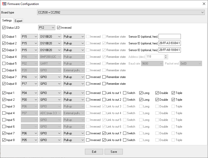
- The firmware supports up to 8 GPIO inputs or outputs.
- The “switch” mode for inputs.
- Pull-up and Pull-down options for inputs and outputs.
- Analog inputs.
- Internal temperature measurement.
- Source voltage measurement.
- UART (only text commands between an external device and a host, look at README.txt).
- Simple MODBUS master implementation (reading sensors).
- Some environmental sensors (DS18B20, BMP280, BME280, DHT 11, DHT 22, DHT 12, AM2301, Sonoff SI7021, MHZ19, SenseAir S8, Sensirion SPS30, SI7021 (I2C), CCS811).
- BH1750 (Ambient Light Sensor).
- PZEM-004T (Energy Monitor Sensor)INA219 (DC Voltage/Current Sensor), INA3221 (3-channel DC Voltage/Current Sensor), ACS712, ACS758 (Current Sensors)
- Pulse generator.
- Pulse counter (infinite, resettable, interval).
- PWM (hardware, up to 128 kHz).
- PWM (software, up to 3 kHz).
- Bi-stable relay.
- Watchdog timer.
- Configurable default reporting interval.
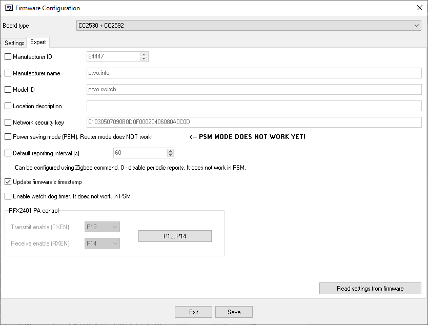
- Expert options (model ID, manufacturer info, network key, etc.).
Download
Your comments and bug reports are welcome :-)!
Changelog
The detailed changelog is placed on a separate page.
 Owner
Owner
Olili
Dear ptvo,
thx. I had a another look into the datasheet. I try to summarize:
Inputs are configured as “tristate” (high-z) for external pull-down, external pull-up, and tristate.
Default Logic is low active, ie. 0V = pressed.
In case of selected “inverted” it is high active (3V3 = pressed) ?
Correct?
If yes, I think the “inverted” feature is not working…it has no impact on logic.
Wrt to outputs: understood your hint. According datasheet in output-mode all powerstages are push/pull ones. So I assume there is not really an impact of tristate, pullup …. on the behavior. Correct?
Brest regrads, Olili
Owner
1. I _suppose_, that inputs are configured as “tristate” (high-z) for external pull-down, external pull-up. It is necessary to check a data sheet for the default mode of pins.
2.
>>>In case of selected “inverted” it is high active (3V3 = pressed)?
Yes.
3. I cannot answer precisely. It depends on your schematic. For outputs, the default logic is HIGH => 3.3V, LOW => 0V.
Olili
Dear ptvo,
I’m once again struggling ewith the input logic.
I have signals with high active (3v3 = pressed). I was not able to get it run configured as pull-down, pull-down external and tristate in the combination inverted and non-inverted.
What I’m doing worng?
I have still problems to understand your naming for the input:
internal pull up, internal dull-down and high-z (=tristate?) for an input I can understand. But how are inputs configured in case of external pull-ups/downs?
My understand that your logic is basically a low active one. This means 0V = pressed, right? What is the meaning of “inverted” exactly?
Btw: I also have some problem to understand the GPIO-config for output. I know low-side, high-side and push/pull. How does this fit to pull-down, pull-up and tristate?
Best regards, olili
What is the difference tristate and pu
Owner
Hi! I use terms from the CC2530 datasheet. Where “high-z” == “tristate”. When you select external pull-up or external pull-down (https://en.wikipedia.org/wiki/Pull-up_resistor), the firmware does not change the pull configuration of pins and uses default values (I think, it is tri-state). I don’t know what you mean by “low-side, high-side”. Yes, the default logic supposes 0V = pressed, but if you select “inverted”, the firmware inverts that logic.
Dieter
Hi, great project. If I get it right, I could – once you have mastered the battery mode – implement my project: I have a battery powered actor that should sleep most of the time. Once a command is received, the actor wakes up, does its job and falls asleep again. Is this, what PSM mode can Do? If yes, can you help me estimate, how much drain that generates – assuming checking every second. I guess it works similar to BTLE advertising? Thanks heaps.
Owner
Hi. Sorry, but I cannot estimate the power drain right now.
David
Hi
Having a bit of trouble getting the pulse counter working, I have the following Output configured:
P03, Counter, Pull-Down, Interval (sec) 0
But regardless of how many times I briefly connect P03 to VCC (to create a rising edge) the value reported by the module never changes from zero…
Any suggestions as to what i’m doing wrong?
Cheers
Owner
Hello. Did you wait for a reporting interval?
David
I did indeed, defaulting to 60 seconds. I get readings from my DS18B20 just fine, just zero for the pulse count values:
‘attributeReport’, cluster ‘genAnalogInput’, data ‘{“presentValue”:0}’ from endpoint 3 with groupID 0
Owner
Ok. I’ll look at that.
David
Cool – thanks 🙂
David
Hi, so did anything jump out as to why pulse counting is not working?
Owner
@David, the latest version of the firmware works in the counter mode (both, pull-up and pull-down). If it does not work in your case, please, post a link to your configuration.
David
Sure, here is my config:
https://ibb.co/HCmtTc5
Under the export tab I have set a Manufacture name, Model ID and a Default reporting interval of 60 seconds
Thanks for any help you can give 🙂
David
ermanue
Hello, you’ve done a great job!
I think, as Charly said, a toggle mode would be very useful, like the aqara dual-switch does. This one also has an interlock mode to prevent two outputs from being active simultaneously, could you implement something like this?
One last thing, I can’t understand how the counter configuration works for an input, when it sends the result?, how it is configured for infinite, resettable or interval?
Thank you very much for your time and for your work !!!
qlwz
how to Re-pairing?
Power on, wait 2 seconds, power off, repeat this cycle three times.
This operation is very bad
Can you associate keys
Owner
You may configure a GPIO button on “Input 1”. Disable the switch mode for that input. That button works as a system button. Press and hold it 10 seconds for reset.
Leo
Hey i wonder if it work with this board that its for adding a cc2530 with battery and pinout etc.
https://www.aliexpress.com/item/33026257011.html?spm=a2g0o.detail.1000060.3.2030ca2dOEt69d&gps-id=pcDetailBottomMoreThisSeller&scm=1007.13339.146401.0&scm_id=1007.13339.146401.0&scm-url=1007.13339.146401.0&pvid=5cce97c5-67bd-47d1-adf5-f9c796ae120c&_t=gps-id:pcDetailBottomMoreThisSeller,scm-url:1007.13339.146401.0,pvid:5cce97c5-67bd-47d1-adf5-f9c796ae120c,tpp_buckets:668%230%23131923%2316_668%23808%237756%23669_668%23888%233325%236_668%232846%238114%23754_668%232717%237560%23241
Owner
Hi. It is an expansion board for CC2530. So you may use it without any problems.
Vasiliy
Hi, when do I plan to add PSM for working with batteries.
Owner
Sorry, but I cannot estimate the release date.
Fabian
Hi
I did that already but it’s still an old version.
I also tried with Edge I am not suing so there is zero chance I ever download this file and it’s also the old version.
Maybe it’s better if you could include the version in the file name like that there won’t be any confusion at all.
Thank you
Andreas
@ptvo FYI, CNX Software has posted a blog post mentioning your Zigbee FW tool https://www.cnx-software.com/2020/05/25/zigbee-firmware-news-ti-z-stack-3-0-zigbee-for-cc2530-ptvo-zigbee-fw-configuration-tool/
Fabiancrg
Hi,
It seems the download link points to an old version, could you please check ?
Thank you
Owner
The link points to the latest version. Some browsers can cache the file. Please, clear a cache or force re-download the file.
Toni
Thank you for the answers. I have additional wish, if it is possible. Is it possible to add to DS18B20 option, that it reports if the temperature change for some dT? So that it would respond on some defined interval, ala 60 minutes and if there would be change in temperature it would also report. If this would be added and deep sleep, than this could be an end device running on battery. What do you think? Similar to Aqara termometer, that runs for more than a year on one battery.
Regards,
Toni
Owner
In any case, the module should wake up to poll the sensor. So, it will not save battery power. Currently, the firmware is not optimized for battery power at all.
Toni
I don’t know how it is at this module, but I guess if you only start onewire and calculate the difference of the previous and new measured temperature, without turning the transmitter on, it shouldn’t consume so much energy, or not?
Regards,
Toni
Owner
Maybe. I didn’t try it yet 🙂
Toni
Dear all,
when I download new program to configure firmware, I can only see pin-drop down menu and pull-state drop down menu. There is no drop down menu to select type of output/input (like GPIO, ADC, etc.). The filename is: cc2530_io_1.2.2a.44539_firmware.
Is it an old link?
Regards,
Toni
Owner
Hi. Some browsers can cache the file. Please, clear a cache or force re-download the file.
Toni
Dear all,
I want to connect DS18B20 to pin 15 on my CC2530 + CC2592 board. How to set the pin status (Pull-up, pull down, …). Do I need to add 4.7K Ohm or 10K Ohm resistor?
Regards,
Toni
Owner
Hi Toni. Select internal pull-up for a short cable length (up to 1m) and external pull-up (4k7 Ohm) for longer cables.
Olili
@Giovanni,
I had also some big problem to pair ptvo devices with my z2m network.
Finally re-flashing the z2m firmware solved the the problem for me! Really
In this case it is not necessary to re-pair the existing devices of your network.
Giovanni C
hi, I’m struggling to have this firmware working on ebyte E18-MS1-PCB, no matter what I do the pairing does not complete with this error:
“zigbee2mqtt:error 2020-05-17 16:58:50: Failed to interview ‘0x00124b001f853fd6’, device has not successfully been paired”
I even try to configure NOTHING to have a simple ruoter and same error.
If I use your “router only” firmware on the very same device all works perfectly 🙁
What am I doing wrong? Can you help me please to understand at least where to look at to solve this problem? It’s a pity as I’d like to use this firmware by unable to do (maybe I’m too stupid and missed something obvious… 🙁 )
Owner
Hi Giovanni,
Sorry, I don’t have any ideas. Did you select the correct board type in the configurator?
Giovanni C
Yes I did and did several tests, as I said even with no input and no output enabled (to have a pure router as you suggested to me in the past) and the device cannot be paired with the same error 🙁
I’m stuck…
I just saw you released v2.4, I’ll try this new version to see if any changes and let you know
Owner
If Z2M added a device ID to a database, but you’ve changed the device configuration, Z2M cannot update info about that device. It is necessary to remove it from a database manually.
Patrick
Hi, really like what you made here.
I have a question regarding pairing. Is it only possible to pair the device if i set up “zigbee2mqtt”?
I got Home Assistant with deConz (Conbee II) set up as Zigbee coordinator. Would it be possible to pair the CC2530 with my Conbee II stick?
Owner
Hi Patrick, the firmware searches for a first open Zigbee network and tries to join. I didn’t work with deConz before and I cannot answer precisely.
Patrick
Thanks for the fast reply.
No problem, i will try a few things and maybe set up zigbee2mqtt later to test.
Thank you 🙂
Miguel
My board with RFX2401 Amp is labled BHZ 2530CA.
RXEN is controlled by P2.0 and TXEN by P1.2.
Which firmware should I use?
Owner
Sorry, but you cannot use my firmware. The firmware does not support your hardware layout.
Live
Thanks for your work!
Question: the instructions say:
“If you configured first input pin, click and hold it for 10 seconds”
But, if 1 input pin is in switch mode, then what will happen?
Owner
Hi! In that case you cannot use Input 1 for reset.
Roberto
@Charly, can you share link of ZigBeeOnOff switch !☺️
Roland
Nice to see the PWM feature showing up in this release, can you give an example on how to control these outputs? It’s not in the readme.txt. Thanks.
Owner
Hi Roland.
Please, look here: https://ptvo.info/zigbee-configurable-firmware-features/
Levon
Hi, unfortunately i am also struggling to understand PWM control from the page you are referring to.
I am able to control PWM in linked mode, controlling the width of pulses with 12 step cycle by switching the input pin. Same works from Home Assistant GUI.
As i understood from the the link above, PWM value can be from 0 to 255, but i do not understand to which topic should i post these values and what is the format of the message.
Can you please share an example?
Thanks in advance!
Owner
Simply write a value (0-255) to the corresponding output. Sorry, but I don’t know how to do it in HA. For example in Z2M: Output 1: zigbee2mqtt/[FRIENDLY_NAME]/bottom_left/set => value
Levon
Hi, thanks for looking in.
I already tried that prior asking, unfortunately no success.
Maybe i am wrong but it seems that the topic you are referring to is the input, and it accepts only ON or OFF values (and this is working, PWM is changing cyclicly as you described in manual, though i counted 13 cycles before it starts over instead of 10 as stated in documentation).
All other numeric values posted are being silently ignored.
I tried to publish values both via HA and through MQTT explorer app with same results.
Below is my configuration, Maybe i am not fully understanding the concept of input/output?
“`Board type: CC2530 + CC2592
Manufacturer name: ptvo.info
Model ID: ptvo.switch
Update firmware’s timestamp : 2020-05-31
Power saving mode (PSM): No
Status LED: Yes
Default reporting interval (s): 60
Output pins:
P17: Output 1, PWM (Software, 1 KHz), Pull-up, Remember state
P20: Output 2, PWM (Software, 1 KHz), Pull-up, Remember state
Input pins:
P02: Input 1, GPIO, Pull-up, Link to out 1
P03: Input 2, GPIO, Pull-up, Link to out 2
“`
Thanks one more time for your time.
P.S. Status led is configured at P01
Owner
Oh yes, if the input is linked to the output, then it does not work. It is necessary to modify the Z2M converter to use the “ZCL_CLUSTER_ID_GEN_LEVEL_CONTROL” cluster.
imod
Hi, i am really impressed by this great project!!
I try to get some cc2530 modules running in ioBroker but struggeling a little bit.
I modified the devices.js and now my outputs are working.
But i don’t get the input states. The genMultiStateInput throws a timeout error. Does anybody have me some hints :).
Thanks…
Marco
Hello, thank you for your effort. I am trying to control an 8-channel relay module, but it has active low inputs. GPIO initial state pins are at low level …Could you add an option to set the GPIO pins state at startup or an inverted option like for the led?
Am I missing something? Thanks.
Owner
Hello Marco. I’ve added the “Inverted” option.
Marco
Thank you for the realtime update, but at first try the outputs are not inverted (pull-up/inverted) and if I load the firmware settings from the HEX it doesn’t match my saved configuration…
Owner
Can you configure all the settings from scratch and upload to the device? Could you show your settings?
Marco
I tried without success with just one output. If “Inverted” is selected, saving and loading again the firmware settings shows no pin number.
https://pasteboard.co/J6VOi32.jpg
https://pasteboard.co/J6VOwlQ.jpg
Owner
I’ve fixed the bug with the configurator. I’ve tested your settings. The “OFF” state involves the “HIGH” state on the output.
Leon
Thanks for your reply,
I will have a look at it.
Leon
I am looking for an scheme for connecting an simple on off switch to an cc2530. There are very much schemes on github but none of them is working normal.
Owner
Hi Leon.
Sorry, I’m a software engineer. Maybe you can find useful schematics here.
https://modkam.ru/?p=1309
https://modkam.ru/?p=1054
The website is in Russian, but you can easily translate it with Google. Both devices are widely tested by the Russian community, with my firmware too.
Olili
MAybe I can help:
select a unused GPIO, eg P14.
Configure it as internal Pull-Up. Connect the switch between P14 and GND.
Alternatively you can configure the GPIO to internal Pull-Down. Then you have to connect the switch with the GPIO and +3V3.
Please take care that you do not use a GPIO that is already in use for e.g. controlling the amplifier like P1.1, P1.0, P0.7 in case of CC2592-boards.
Standard for all boards: Pin 1 to GND, Pin 2 to 3V3, Reset not connected.
Leon
Thanks a lot, i have it working right now!!!
Roland
Great project, thanks for the work you put into this. Just build basic switch node with a Ebyte E-18 module and it works. I’m using zigbee2mqtt in combination with node-red. Looking forward to the power save function.
Olili
Dear ptvo,
I played around with your v2.2. In sum: great work!
Nevertheless I’m still struggling with the switch button / input logic.
I need 3 inputs which have high-impedance (ie. tristate) and are active high (ie. GND = button released, 3v3 = button pushed).
Until now I was only able to get get this behavior with inverted logic, ie. 3v3 = button released, GND = button fired)
Any hint?
Furthermore I tried the “switch”- input feature. Is this feature already supported by z2m converter scripts? After configuring all simple buttons as “switch”, they were somehow dead. Any hints wrt this?
olili
Owner
1. Input. Did you try the pull-down mode?
2. Switch. I have tried it in conjunction with an output. Z2M supports on/off states.
Olili
@ptvo,
yes, tried it with the external pull-down mode. Logic seems still to be low active.
Is there an difference to internal pull-down?
Wrt “Switch”: you have directly linked the input to an output and use state of the output, right? And if you do not want to link it an output?
Olili
Owner
With internal pull down the firmware inverses logic.
Switch. You may leave output pin unconnected, like a virtual switch state.
Olili
Thx, internal pull-down is working.
I would recommend to separate logic (active low/high) from electrical input/output characteristics ( pull-up, pull-down, high-z).
Additionally I would define different characteristics for gpio input and output:
input – pull-down, pull-up, high-z (tristate)
output – low-side, high-side, push/pull
Thx and best regards, olili
Martin
I’ve tested this. I can link an internal pull down as switch to a output, the input is reversed. But it is not possible to reverse an output. I’ve relais connected wich are active low.
There is an other problem, when you use internal pulldown, you can’t use the status LED on the same port
Robert
Very nice project!
Using a CC2530 card and this firmware, I can drive a IR LED to send codes (like remote controller)?
(I m a newbe, sorry if my question can be ridicolous)
Owner
Hi. Sorry, you cannot do it.
Olili
I tried to make latest version v2.2 running on several E18-MS1-PCBs (CC2530+CC2592) with several configurations. As P1.1、P1.0、P0.7 are connected with CC2592 pins I have not used these 3 pins in any configuration.
Nevertheless until now I was not able to pair it with my Zigbee-Network.
With my own SW the devices are pairing without any problem.
Any hint?
Olili
Olili
I have a problem to get latest V2.2 running on a E18-MS1-PCB (CC2530+CC2592).
It’s is simply not joining network or showsing any transmission attempts.
Tried different configs. My latest config attached:
Board type: CC2530 + CC2592
Model ID: Fingerprint
Power saving mode (PSM): No
Output pins:
P03: Output 1, GPIO, External pull-up
P06: Output 2, GPIO, External pull-up
Input pins:
P12: Input 1, GPIO, External pull-up
P14: Input 2, GPIO, External pull-up
P17: Input 3, GPIO, External pull-up
I had no problems with V1.1 in combination with theses chips.
Any hit?
Thx in advance.
Olili
Owner
Hello Olili.
Does your board have “External pull-up” on input pins? The previous version used the “Pull-up” mode by default. Try to change the pull-up mode. Try to shift input pins and do not use Input 1.
Olili
thx. I removed every input now and only configured one output with internal pull-up. Additionally I tried it now with a board without CC2592 Amplifier (in addition to my E18s). Within Expert-Setting I only enabled ModelID to “Fingerprint”. Everything else is disabled.
But until now no improvement. I’m not able to pair with your firmware. Everything else is working well within my zigbee network. I’m also able to add non ptvo devices.
any hint?
Olili
Owner
You’ve changed ModelId. In this case, Zigbee2Mqtt will not detect the device. I’ve checked the firmware for cc2530+cc2592. It works as expected and joins to Z2M.
Olili
issue resolved. Problem not with your great firmware!
Coorrdinator (Z2M) had to be reflashed. Somehow not enough space for further pairings …. now everythig works as expected. Many thy for your support!
Oli
Daniel
You did a really good job with the tool. Many Thanks.
It is possible to include CC2538 + CC2592 in Firmware Configuration Tool?
Owner
That chip is fully different. I cannot create the firmware for it.
Fabian
Hi,
I am testing the new firmware but have some issue to connect a BME280 using I2C.
I have two connections on my PCB; P0.5 and P0.6 on which I want to connect SDA and SCL but I see I can choose to define them asoutput and as input. When defined as output, I can enter the I2C address (118) but not in input.
So is it an input or an output ?
I tried both but nothing is reported.
Thank you
Owner
Please, define as an output. Did you check the sensor with other board (e.g. ESP8266)?
Fabian
Yes, the sensor works, I connected it to an Arduino but it’s a BME280 and not a BMP280 (according to readme, BMx280 are supported, is it correct?). It’s accessible using I2C address 0x76 (118).
I retried as an output, removed it from Z2M before flashing and pair it after but nothing is reported.
In the tool, I used ‘Output 7’ for DMP280(I2C SDA) linked to P06 with address 118 and ‘Output 8’ for I2C SDL linked to P20.
Are these ports OK or do I have to select some specific ports for I2C communication?
Is there a way to debug something ?
Fabian
It’s working now, apparently problem was due to the DS18B20 I configured too.
If I use a DS18B20 as input and a BME280, only the DS18B20 temperature is reported as L2.
If I define only the BME280, I get the report but everything is reported in L7, is it normal ?
So it seems the BME temp, pressure and humidity are reported one after the other and not separately.
Owner
Define these sensors on different outputs. Yes, the firmware reports all values on one endpoint but with a different description. The description includes units and device ID.
Charly
How can you configute the reporting interval in zigbee2mqtt? I cannot find out the right json syntax. Can somebody briefly explain? Thank a lot and please continue with this project.
Owner
Please, look here
https://github.com/Koenkk/zigbee-herdsman-converters/blob/37716aaa144c56594730cd95fcda7d2947541f41/converters/toZigbee.js#L1633
Philip
Thanks so much for your effort! I’ve successfully used your previous firmware configurator for my cc2530 modules and cc2530+cc2591 modules. This is sooo easy and useful 🙂
This time I’ve just tested it briefly because I use ConBee and all newly implemented features can’t be consumed via deCONZ. However I see the clusters with attributes that do make sense (e.g. power source measurement). So cool!
I can’t wait for dresden elektronik to finally support zigbee2mqtt so I can use your configurator not only to control relays/outputs, but also to do my DIY sensors in a places when I don’t have WiFi coverage. That is so perfect. Many thanks for sharing this with us!
One thing that I may want to see is a little bit more comprehensive explanation how some configurable options work with their purpose. Unfortunately not all is perfect clear to me.
Examples:
– default vs. pull-up vs. pull-down differences
– some expert settings: PSM, firmware timestamp, watch dog timer
Thank you again!
Owner
First of all, you should look at the datasheet for the CC2530 chip. There are much useful information.
default vs. pull-up vs. pull-down – default the default state of the pin, when CC2530 starts. pull-up – the unconnected pin state is “HIGH”, pull-down – “LOW”.
firmware timestamp – the Zigbee device information has that attribute. You may place your date code there.
Giovanni C
Thanks a lot, this project is awesome!!
I’ve a small request, is there any chance to implement a PWM output?
I would like to control RGB Strip led and be able to dim them…
Owner
Thank you for testing 🙂 What parameters of the PWM output do you need? I cannot guarantee precise timings for PWM impulses.
Giovanni C
well an RGB strip is normally controlled by one or more PWM signals, 95% of the time it’s one only (single color strip) or three (RGB strip), those are the 2 type of commands the module shoudl listen to when used for PWM/StripLed control
Owner
I didn’t work with PWM and RGB strips before. I should know how long is the period of impulses in milliseconds.
Giovanni C
the highest the better 🙂
ESP8266 frequency of 1kHz is barely enough, ESP32 I can go up to 10kHz and it’s much better with no flicker
darksimpson
Do you think about making your project available to open source community? At least it will widen a community of such a good project, and many features will be implemented by other members.
Personally, I need a some kind of low power mode and this is a must for me, because I want to implement many battery powered applications in my house (oh, and I will not use mechanical relays for this of course). In case of open-sourced project I could implement this and contribute to community and in case of closed-source project I forced to wait when functionality will be added by owner.
Anyway, thank you for your great work!!!
Charly
But according to the datasheet while in RX mode TXEN (P12) must be low. TXEN must be high only in TX mode, similar to PAEN of CC2590. Can your FW support such a modification? Simply need to assign TXEN/PAEN from P11 to P12 instead. Datasheet: https://www.skyworksinc.com/-/media/SkyWorks/Documents/Products/2301-2400/RFX2401C_204359B.pdf
Owner
When TXEN=1, RXEN does not matter. It can be “1” too.
Owner
I’ve added support for RFX2401 PA. Could you please re-download firmware and test it with that board?
Charly
I tested the new FW with the RFX2401 support quickly and it seems to be working fine. Great job! I will continue testing. (Now I can easily “hack” an inexpensive ZigBeeOnOff switch and can use its reset button for toggling the relais.) Thanks a lot!!!
Roberto
Interesting! Can you share more info about ” ZigBeeOnOff switch”?
Owner
Hi. What exactly would you like to know?
Charly
There is a popular zigbee module https://ae01.alicdn.com/kf/HTB1Y3NMaUY1gK0jSZFCq6AwqXXaa.jpg using the RFX2401 PA controlled by P14 (RXEN) and P12 (TXEN). This is different from the typical CC2590 modules using three signals P11 (PAEN), P14 (EN) and P07 (HGM). While RXEN (P14) can be set to permanent high, TXEN (P12) needs to be enabled during Tx only. Can you provide a special FW flavour for this type of module? It is used in the popular ZigbeeOnOff Switch (https://www.zigbee2mqtt.io/devices/KS-SM001.html) and could be easily flashed and enhanced with your great config tool. I volunteer for testing if needed. Thanks for considering!
Owner
Please, note that ZStack SDK disables RXEN and TXEN only when CC2530 goes to the sleep mode. So, mostly these pins are high.
Arm.
In the previous version, it was possible to select BMP (SDA) and BMP (SCL).
How to connect the BME280 sensor in this version?
More than one DS18B20 sensor connected in one line does not work.
Owner
Select BME280 first (it is the SDA pin), then define the I2C SCL pin.
DS18B20 – I’ll test it.
Arm.
BME280 sensor continuously outputs a value
here is the log
https://pastebin.com/Qs5zAgV6
The default reporting interval is not working correctly.
At any value (except 0) it reports about 22 seconds.
Owner
Is it possible you send the “read” command to the device?
Arm.
No.
Arm.
For the MHZ-19 sensor in the configurator I set it like this
P03: Output 7, MHZ 19 (not tested)
P02: Output 8, MHZ 19 (not tested)
What should I choose in Address (dec)?
Owner
Hi. Leave the default address ‘1’.
Arm.
connected the MH-Z19 sensor so
CC2530 P0.2 -> MH-Z19 RX
CC2530 P0.3 -> MH-Z19 TX
works great
Owner
Hmm. Strange :). First test and it works. Did you get values in zigbee2mqtt?
Arm.
I get the value in the SLS Gateway.
In the configurator set so
Output pins:
P10: Output 1, MHZ 19 (not tested)
P13: Output 2, DS18B20
P16: Output 3, Source voltage
P14: Output 5, Internal temperature
and here is the log
https://pastebin.com/Pfrr257T
Owner
Great!
Schmurtz
This is really awesome. It’s like a start of ESPhome for CC2530 instead of ESP8266.
I mean it allow to create a zigbee device with a simple interface (like esphome allow to create a wifi device without coding).
Is it possible to make device wich work with battery (like CR2032) ?
Owner
Hi, my firmware does not support the battery powered mode yet.
Graffiti
Hi,
I am working on DIY bulb project and wanted to know how you implemented the repairing mechanism.
“Re-pairing
=========================
Power on, wait 2 seconds, power off, repeat this cycle three times.”
could you share the code for this section?
Thanks
Owner
Hi, Sorry, but I cannot share sources. You need to check, increase and save a counter to NV ram. Start a timer for 5-7 seconds and reset the counter.
Charly
First of all, great project. Thank you very much for your efforts! I have one suggestion for the “switch” mode input: Would it be possible to add an option that toggles the linked output every time the switch changes its status? I.e. even if the output is On and the switch goes from Off to On, then the Output toggles (from On to Off). The Xiaomi LLKZMK11LM relay does the same (https://www.zigbee2mqtt.io/devices/LLKZMK11LM.html). It would allow to control an output by both the coordinator and a standard wall switch (as opposed to a push button). Thanks!
Owner
Hi, but in this case, the physical position of the switch will not reflect the state of a light.
Charly
Correct! But it allows to add a smart “PTVO-Switch” to an existing installation and control the light by the coordinator and still use the legacy wall switches. E.g. turn off a light that the user left on and still the user can turn it on again by turning the switch normally (sorry, I don’t know the right name for such mode if it exists).
Owner
Hmm. I’ve tested the switch button. It works as you described. I can control the output state through MQTT while the button is pressed. Could you please describe your test scenario? Could you attach a screenshot with your firmware settings?
Charly
Yes but … this is not exactly what I mean. I tested it again. Here is a scenario:
1. Output 1 is connected to a relay, Input 1 is connected to a physical wall switch (not a button)
2. The wall switch is turned on -> Output 1 goes ON – perfect!
3. The coordinator turns Output 1 OFF (e.g. staircase lights after timeout) – perfect!
4. Now the user comes back and wants to turn Output 1 ON again by turning the wall switch (that is still in ON state, so its turned from ON to OFF) –> nothing happens!
Instead the user has to turn the wall switch twice (ON->OFF->ON) to turn Output 1 ON which is less ideal. (Not a big thing but a small but “smart” difference to most other smarthome devices, except the Xiaomi LLKZMK11LM relay that does exactly what I mean but doesnt’t fit in a wall hole)
This is my setting:
Status LED: Yes
Output pins: P10: Output 1, GPIO, Pull-down, Remember state
Input pins: P00: Input 1, GPIO, Pull-down, Switch, Link to out 1
Thanks!
Owner
I think the current behavior is more related to physical switches because they have fixed positions for ON and OFF.
Charly
Yes, you are right. But I was wondering if you can add a “toggle” _option_ to the switch mode, that meets the desired behavior. Would be great! Anyway, thanks again for the great work.
Bo Christiansen
Hi, I was wondering if it will work with groups in such a way that it can work even if the zigbee coordinator is down ?
Owner
Hi Bo,
The firmware does not support groups.
Evhen
PSM MODE DOES NOT WORK YET – really want to get battery power. I will wait for a future release.
Owner
Thank you! I’m working on it.
Suprimex
Many thanks!!! Already tried it, paired with zigbee2mqtt without any problem. But can you point me, how to set outputs from 2 till 8? As far as I understand , I can set Output#1 with topic
zigbee2mqtt//set , with payload “ON” . But how to turn on/off others ?
Owner
Hi, you may use l1..l8 for output On/Off channels. For example
Suprimex
Unfortunately this method not working, zigbee2mqtt throw error:
debug 2020-04-03 12:53:42: Received MQTT message on ‘zigbee2mqtt/ptvo01-ledlamp1/l2/set’ with data ‘on’
error 2020-04-03 12:53:42: Failed to call ‘EntityPublish’ ‘onMQTTMessage’ (AssertionError [ERR_ASSERTION]: Postfix ‘l2’ is given but device has no such endpoint
Owner
You should use the latest developer build of zigbee-herdsman-converters.
xfndx
Can is support 8 inputs ?
Owner
The standard ZStack SDK supports 4 buttons (inputs) only. Therefore I’ve implemented 4 inputs.