 Owner
OwnerThis firmware allows you to create a Zigbee switch device with a flexible configuration of inputs and outputs. I’ve created a base firmware for CC2530, CC2530 + CC2590 , CC2530 + CC2591 and CC2530 + CC2592 chips. The attached configurator for Windows can write your device configuration to the selected base firmware. Then you can save the customized version to a separate HEX file and upload it to your device.
Inputs and outputs can work independently. So you may create a switch without a control button, or a simple button only.
The device with this firmware also works as a router.
Note: the firmware is designed for constantly powered devices.
Options
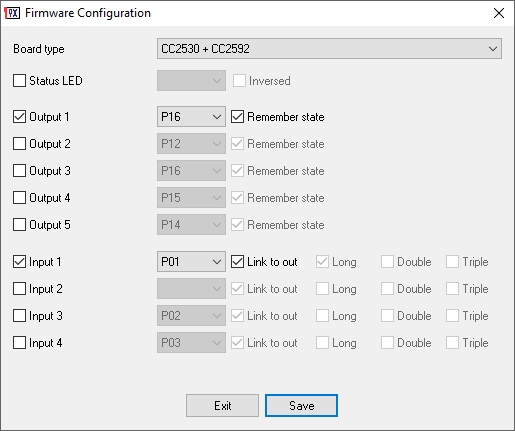
Remember state – The firmware saves the output state to NVRAM and restores it after power off/on.
Link – The input immediately controls the state of the corresponding output. The device sends the on/off state of the output to a coordinator. Otherwise, the input is independent.
Long – The firmware detects and reports to the coordinator a long click (2000 ms).
Double – The firmware detects and reports a double click (max 500 ms between clicks).
Triple – The firmware detects and reports triple-click (max 500 ms between clicks).
Zigbee internals
- The firmware creates a separate endpoint (1..5) for every configured output and/or input (max 5 endpoints).
- The firmware reports the state of an independent button via the “ZCL_CLUSTER_ID_GEN_MULTISTATE_INPUT_BASIC” cluster and the “PRESENT_VALUE” attribute. 1 – single click.
2 – double click.
3 – triple-click.
4 – long click. - The firmware does not send a separate report for the linked button. Otherwise, it sends reports about the output state via the “ZCL_CLUSTER_ID_GEN_ON_OFF” cluster and the “ON_OFF” attribute.
- You may control the output state via the “ZCL_CLUSTER_ID_GEN_ON_OFF” cluster and the “ON_OFF” attribute.
- The “ZCL_CLUSTER_ID_GEN_ON_OFF” cluster also accepts the “read”, “configure” and “onOffWithTimedOff” commands: “read” – returns the current state on the specified endpoint.
“configure” – set the periodic reporting interval for the output. The “minReportInt ” attribute specifies the reporting interval in seconds. If “minReportInt ” is 65535, the firmware disables periodic reports. “onOffWithTimedOff” – sets the output state to “HIGH” for “onTime” milliseconds, and automatically resets to “LOW”.
Updates
2020-04-01 Released v2.
2019-08-14: Fixed bug with 3rd and 4th inputs.
2019-06-27: First release.
 Owner
Owner
Olili
for you next release I suggest to enable LQI scan.
Simply add
#define ZDO_MGMT_LQI_REQUEST
#define ZDO_MGMT_LQI_RESPONSE
to preconfig.h
That should be enough. Best regards.
Owner
Hi,
I’ve double checked. Both defined are active.
Jel
As other people have stated, status led does not seem to work.
I have configured the firmware with five outputs and the status led. I tried different pins for the status led but none of them works.
To test it, I have used a limiting resistor with a led in series ( same circuit that I have used to test the outputs succesfully).
Any idea why the status led doen’t work?
Archibald
Hi. Many-many thanks for your work! 🙂 Your work is very interesting and informative for me. But I’m quite green on zigbee diy devices. Please tell me how to connect the button correctly?
Sewed firmware and pins like this https://take.ms/tzck4
So I tried to connect the board https://take.ms/KizDL
Owner
Hi, Connect P00 to 3.3V through 4.7K pull-up resistor, and to GND through your button.
Stephan
Hi there!
Thanks making this awesome firmware available for us to use!
Would you be willing to make the firmware open source and publish the source code to GitHub?
Thanks 😄
Owner
Sorry, but I’m not ready to publish the sources.
Hedda
Any chance that you could release Z-Stack 3.0.x router firmware hex bin files for CC2530 and CC2531?
https://github.com/Koenkk/Z-Stack-firmware/tree/master/router
The reason is that that would like to use some CC2530 and/or CC2531 as Zigbee 3.0 routers.
Is it even possible to use CC2530 or CC2531 hardware as Zigbee 3.0 routers with other firmware?
Owner
Hi, Zigbee 1.2 router can be used in Zigbee 3.0 networks. Do you need something special from Zigbee 3.0 routers?
Hedda
Hi, I posted a more detailed request for Z-Stack 3.0 router firmware on Koenkk’s “Z-Stack-firmware” repository on GitHub which hosts some of your firmware hex files:
https://github.com/Koenkk/Z-Stack-firmware/issues/153
Point is that would like to use CC253x based hardware to make a fully Zigbee 3.0 complaint router device, without the end device having to run in ZHA backwards compatibility mode.
As I understand, that way the router would be able to route other Zigbee 3.0 protocols than just ZHA. Like for example ZLL.
suprimex
Many thanks for your work. Impatiently waiting for battery-powered version.
Mudi
Hi,
thanks for your work, I really see the benefit for the ZigBee systems.
I would like to adapt the sources by myself, but I also respect that you don’t want to share them.
My request is, if it is possible to make the cc2530 a UART bridge for the e.g. Arduino. So that I can send a custom status message or measured values (CO2 Sensor) to the coordinator and vice versa via RX TX.
I would have to use a second microprocessor, but this would make the whole thing more flexible.
What do you about that?
Thanks
Owner
Hi. My firmware cannot do it. It is possible you may find a specialized ZigBee device on Aliexpress.
Christoph
Hallo,
Ich habe ein Proplem mit der Software.
Ich verwende E18 MS1PA1-PCB (cc2530+cc2592)
aber wenn ich bei der Software das auswähle dann blinkt die Led gar nicht nur bei cc2530+2590 und 2591 blinkt es aber zigbee2mqtt findet das gerät nicht.
Pim
Heya – playing around with your firmware (CC2530 + CC2592). I noticed that the firmware also responds to ‘TOGGLE’ commands when driven via z2m, however, the firmware does not send a state update when receiving TOGGLE, even though the channel does switch.
mqtt_pub -t zm-0/0x00124b001ef3ca56/center/set -m OFF
==> info 2020-02-15 22:31:43: MQTT publish: topic ‘zm-0/0x00124b001ef3ca56’, payload ‘{“state_top_left”:”OFF”,”linkquality”:2,”last_seen”:1581802303385,”state_bottom_left”:”OFF”,”state_bottom_right”:”OFF”,”state_top_right”:”OFF”,”state_center”:”OFF”}’
mqtt_pub -t zm-0/0x00124b001ef3ca56/center/set -m TOGGLE
==> No update received on z2m, no pubsub message sent
mqtt_pub -t zm-0/0x00124b001ef3ca56/center/get -m ”
==> info 2020-02-15 22:32:35: MQTT publish: topic ‘zm-0/0x00124b001ef3ca56’, payload ‘{“state_top_left”:”OFF”,”linkquality”:0,”last_seen”:1581802355393,”state_bottom_left”:”OFF”,”state_bottom_right”:”OFF”,”state_top_right”:”OFF”,”state_center”:”ON”,”elapsed”:548}’
The subsequent read reveals that the state is indeed on (and so is the LED on the configured pin). Can you take a look to see if your firmware emits a status update when TOGGLE is executed?
Owner
Hi,
It is expected behavior. I did the toggle command for short time actions (milliseconds).
Inverted
Great work, now I was enable to automate all my blinds in Hassio: https://community.home-assistant.io/t/diy-zigbee-roller-venetian-blinds-automation/170993
Dmitry
Thank you for great firmware! If possible, please add option to act input pin as a switch. And maybe increase number of inputs, even sacrifice outputs.
Swoofz
I have a battery powered zigbee remote controller with 8 buttons and using CC2530F256 chip, tried to pair with Z2M but always failed.
Is it possible to modify your firmware to support my controller? Thanks.
Owner
Hi,
My firmware does not support battery powered devices.
Anton
Hi,
Is this firmware compatible with ZLL? If I flash my Sonoff BasicZBR3 with it, would it work with Hue Bridge or Tradfri bridge?
Owner
Hi,
The firmware does not support ZLL.
Rareș Șerban
I have just found this reddit posts, there is a custom firmware with ZLL support, not sure if/how you can flash it though since I couldn’t find anyone to try it.
https://www.reddit.com/r/sonoff/comments/elpueo/sonoff_basiczbr3_could_support_zigbee_30_or/
Jed anderson
Hello …it is possible configure the “long press” option to 10 or 25 milisec? Make it react almost instantaneously ?
Owner
Hello,
The firmware does not have such the feature. Also, the minumal interval can be 100ms only.
Clarkkent
Hi ptvo,
I’m using zigbee2mqtt for integration with my system, And can I define numbers of endpoint when pairing device?
Owner
Hi,
No, you cannot define numbers for endpoints.
Fry
Hello folks,
has anyone tried a device flashed like this with an Amazon Echo Plus as master device?
I want to build my own end devices using zigbee because of low power consumption.
Thanks for your help.
Stefanne
Thanks, this works 🙂
stefanne
Hi, great work was really easy and fast to start with. What Iam struggling with are the attibutes read, congigure … which I cannot get to wrork. Would you mind to post the topic and the messages required in a Mosquitto format?
mosquitto_pub -h 127.0.0.1 -t zigbee2mqtt/0x00124b001efe7bf8/bottom_right/set -m ‘{“state”:”onWithTimedOff”}’
Publish ‘set’ ‘state’ to ‘0x00124b001efe7bf8’ failed: ‘Error: Cluster ‘genOnOff’ has no command ‘onwithtimedoff’
Owner
Hi,
Try the following commands:
mosquitto_pub -h 127.0.0.1 -t zigbee2mqtt/0x00124b001efe7bf8/bottom_right/set -m ‘{“trigger”:1000}’
mosquitto_pub -h 127.0.0.1 -t zigbee2mqtt/0x00124b001efe7bf8/bottom_right/set -m ‘{“state”:”ON”}’
mosquitto_pub -h 127.0.0.1 -t zigbee2mqtt/0x00124b001efe7bf8/bottom_right/set -m ‘{“state”:”OFF”}’
IgorT
The configurator works correctly for the CC2530 but not correctly for the CC2530 + CC2592 chip.
Owner
I’m using these chip myself with this firmware. Could you describe your problem a bit more?
IgorT
The configurator does not change the behavior of pins P1.0 and P1.1 when configured as an output
Owner
Do you use a board with a power amplifier?
IgorT
Yes. I am using the E18-MS1PA1-IPX module (CC2530 + CC2592).
Owner
It seems that these pins are used to control the CC2592 chip.
IgorT
Thanks for your work. With pins understood. But should we expect firmware with the operation of the input pin as a switch (not a trigger)?
Jed anderson
Hi … any new update ? I’ve got my cc2230 modules from aliexpress😁
Grostim
Hi!
Can we have access to the source of this configurable firmware ?
Do the input support direct binding with a specific zigbee group ? (using them as a source in https://www.zigbee2mqtt.io/information/binding.html )
Owner
Hi.
Bad news :(. Sources are not available, and binding does not work.
Nicolas
Is binding with a specific zigbee group still not available? My unsuccessful attempts would tend to show that this is not the case.
Owner
I’ve fixed this problem in the latest version. You can try it to check in your environment.
Jan Mesu
I did set status Led to pin P10 but not working. The output P10 give 1,18V level with nothing connected. This looks like an undefined IO pin. Could you please let me know, if this is a bug or do i something wrong? I use the E18-MS1-PCB module with your firmware and i can switch the output via hassio with z2m, thus that is ok. But the status led wil not work.
Owner
I’ll double-check the status pin. I hope, you didn’t connect a LED indicator to the pin directly.
Jan
Hi,
Thanks for jour answer.
The led is connected to the status pin via a 270 ohm resistor, and the led is a low current led. The output pin of an cc2530 can source the current for the led.
Have you seen the status led working?
Bye,
Jan
Jed anderson
Do you think this module will work with your firmware ? (to make a wall switch)
US $2.97 28%OFF | For CC2530 Wireless Module 2.4G ZIGBEE 3.0-3.6V 2.405-2.485GHz DIY Kits Spare Parts Dropship
https://a.aliexpress.com/b6aPcJWdV
Owner
Hi, yes it will work.
Jed anderson
That will be great!!!
Thanks 👌👌👌👌
Jed Anderson Hidalgo
it is possible change the input behavior from a push button to a switch?
:/ sorry for bugging you
Owner
I’ll add this feature to the next release.
Jed Anderson Hidalgo
ok …i got it … as an example:
1. i link input pin 01 to output pin 12
2. i fisically connect a standart wall switch to the p0_1 and ground of the module
3. i pair the module with z2m
4. i set in home assistant configuration the custom switch
now when i fisically turn on the swith connected to p0_1 and ground of the module nothing happens, only if i turn on and off the switch the state of the module is trigrered. it is posible just fisically turn on to set the switch on in home assistant and vice versa?
Owner
Did you link the input #1 and output #1?
Jed Anderson Hidalgo
i use a cc2530+cc2591 module
the problem , if you may say that, is that the connected fisical switch behave like a push button instead of a switch
Jed anderson
Which outputs are considered dummies?
Sorri about my ignorance …my goal is use a regular wall switch as input and not a toggle button
P.D. great proyect 👌👌
Jed Anderson Hidalgo
what i mean is that right now the input pin acts like a push button not as a switch
Owner
If you’ll link an input to an output, it will act as a switch. You may use any free pin as an output. It may leave it physically disconnected.
Jed Anderson Hidalgo
it is possible use switch mode (to use it as a wall switch) instead toggle mode?
Owner
Yes, it is possible. You should define any dummy output pin and link the input with the output.
John
Can I direct pulse control of output pins? Need send pulse 300-500ms.
Owner
Hi,
Yes, you can do it using the onOffWithTimedOff command on the “ZCL_CLUSTER_ID_GEN_ON_OFF” cluster.
Moritz
Hi, this looks really interesting!
Do you know anything about the power consumption or whether it is possible to run this on batteries only?
As I read in some other comment, the router functionality apparently draws a lot of battery life. Is there a version without routing?
Thanks for your reply!
Owner
Hi,
I’m working on the new version with power saving features.
Serg
Hello! Can I use this firmware to monitor input’s binary state?
For example On/Off toggle switch?
Thank you!
Owner
Hi,
Yes, you can. If you need On/Off, then you should define input and link it to a dummy output (any unused pin). Otherwise, the firmware will detect clicks.
Filip
Can you please recommend me a board with cc2530 and I/O pins that is as small as possible and can be used as end device / router with some sensor or relay attached to I/O pins?
That would be really useful for wall switches or standing lamp switch – need 1 input and 1 output pins.
I am just starting with zigbee, with a little (really basic) experience in programming and DYI projects. So I want to be able to use your solution to easily program routers/end-devices 🙂
Owner
Hi,
Look at the following store: https://www.aliexpress.com/store/2077046?spm=a2g0o.detail.100005.1.6c3f7fb1DicIgE
But pay your attention to the board size and pin density. It is too hard to solder in-home, but it is possible. I’ve created 2 switches using these modules.
Filip
Thanks for your reply!
Which modules are you referring to? They have only one kind of ones with cc2530 🙁
I was thinking about something like that one: https://www.aliexpress.com/item/32881360125.html or that one: https://www.aliexpress.com/item/4000222196626.html
but I suppose that those don’t have any I/O pins 🙁
For me, personally (I’m not that good at soldering), it would be best to have as tiny module as possible but without sacrificing gold pins. I would like to avoid soldering and have a little bit freedom with connecting sensors.
Another question has come to my mind. What input/output voltage/amperage does this boards accept via I/O pins?
Is it possible that you share your circuit diagrams with us? It would be a much helpful resource for DYI newbies 🙂
Owner
For example, https://www.aliexpress.com/item/32640770110.html
Yellows pads around the board are IO pins (look at the last image).
For beginners: https://www.aliexpress.com/item/33009302278.html
Filip
Sure, that’s what I actually get. Maybe I will risk playing with those tinier boards when I get some general practice. I am already waiting for CC2531 and CC2530 module that you linked 🙂
Filip
Also, many thanks for sharing your projects and writing guides. They are much helpful!
Fabian
Hi,
Thnak you for this tool, it’s really nice.
But I do have two issues:
1. I configured P14 as an output and each time I power on the board, it’s toggled ON. Other outputs configured on P12, P13, P15 are OK.
2. If I try to join my lab zigbee network using channel 15 it’s working without any issue. But my other zigbee network is using channel 11 and I can’t pair it.
I do see the board restarting a few times (thanks to problem 1) but after a few times it seems it stays down.
Is there a way maybe to select the channel in the tool ?
Thank you,
Fabian
Owner
Hi,
Sorry about my late reply.
1. Some pins have the default state. The firmware can change it only when it starts.
2. The router scans all channels. But the router may try to connect to another opened network.
Ivan
Hello Ptvo ,
I did set status Leb to pin P10 but not working . Could you please let me know ?
Owner
It is necessary to know something about your schematics.
Inverted
Hi, could you share the IAR *.eww files so that we can tune the firmware more specific
Owner
Hi,
I do not share my sources.
Dmitry
Hello ptvo,
Thank you for your effort to create this filmware.
I’am going to order board and try it. But one thing is unclear for me. Could you please post how to pair this board and how to reset it. Thank you.
Owner
Please, look at the README.TXT in the archive with the firmware.
Massimo Trojani
Hi, is there a domoticz plugins for ptvo.switch?
tnx
Owner
Hi,
I’ve added this device to Zigbee2Mqtt (https://www.zigbee2mqtt.io/). I know you can use Zigbee2Mqtt in Domomticz, but I’m not sure if this device is available there.
Jörg
Hi, It work’s fine with conbee and iobroker. I use it as output with a 4 x relais cluster.
Is it possible to invert the on/off state with the software?
If not is possible to download source?
/jörg
Owner
Invert: it is in my “to-do” list.
Sources: sorry, but it is not available.
Filip
How did you manage to connect it to ConBee/deCONZ? Can you give me some short instructions?
I tried to connect CC2530 with just one output and two inputs configured but it did not work. I could only connect CC2530 with default router firmware installed and it appeared as light bulb.
xjin
Hi,
I used you hex file in my switch(cc2530), but i found an issue on my switch, it is a single wire switch, when it powered on first, the power is not stable, the program seems dead, but it can run normal after reset, so i think can i add a watch dog in the program ?
Thanks.
Owner
СС2530 does not have a hardware watchdog timer. It is not possible to implement.
xjin
Hi,
I have checked the datasheet file, cc2530 has a built0in watchdog timer, this is a description in cc2530 datasheet.pdf (page 1 and page 3, page 21,
http://www.ti.com/cn/lit/ds/symlink/cc2530.pdf).
Owner
Ok. I’ll look at that a bit more in the next version.
fabiancrg
Hi
I am testing this firmware, it’s working pretty well but I cannot find the way to use the read, configure and onOffWithTimedOff.
Which topic and payload do I have to use ?
Owner
Here is the example from Z2M converters:
2
3
4
5
6
7
8
9
10
11
12
13
14
if (!value) {
return;
}
if (key === 'trigger') {
await entity.command('genOnOff', 'onWithTimedOff', {ctrlbits: 0, ontime: value, offwaittime: 0});
} else if (key === 'interval') {
await entity.configureReporting('genOnOff', [{
attribute: 'onOff',
minimumReportInterval: value,
maximumReportInterval: value,
}]);
}
Jaime Vaz
Hi! There is some firmware to create a 4 channel remote using ZigBee witch can be operated using battery? The concept is being always in deep sleep and wake up and send a code when I press a button.
Thanks
Owner
Hi!
This feature is already in my to-do list. But I cannot say when I’ll add it.
Olili
Dear ptvo,
once again many thanks for fixing the “3rd input issue”.
Nevertheless I have to approach you with another request.
I need to configure the i/o-behavior more accurately, i.e. some inputs need to be 3-state or even pull-down.
Therefore, can you somehow offer me an access to P0INP, P1INP and P2INP – init ?
As a quick workaround I can patch the HEX-File by myself manually, but I need respective location of these init values.
Can you support?
On mid term it would be great to make this configurable by your windows application as well.
Many thx in advance,
Olili
Owner
Hi,
Unfortunately, the firmware sets the P0INP, P1INP, and P2INP values dynamically. You cannot change it in the HEX file directly. I’ll try to add this feature to the next version of the firmware.
Olili
Many Thx in advance.
I offer my validation support as soon as you have something available.
MrAlester
Great project! Could you please update it to allow to select the CC2530 as an End Device instead of Router? Please!
Owner
Could you please explain your request? When do you need EndDevice only, and you cannot replace it with a router?
MrAlester
My house (sadly) doesn´t have the Neutral wire on the wall switches.
I managed to flash a non router firmware to a CC2530 and wire the wall switches to a relay that was connected to it. Everything worked perfect, I could turn the lights using the wall switch or a zigbee message.
It worked great until the battery ran out of juice, it lasted one day. That’s when I realized that I needed to configure the CC2530 as a EndDevice. And since I’m not Z-Stack savy, I couldn’t make it work.
My ideal wiring is:
– CC2530 Router at the Lamp Bulb.
– CC2530 EndDevice at the wall switch powered by batteries.
– Wires permanently connected, that way CC2530 Router is always powered.
That way I can use the wall switches that already are placed in the house (wife’s request). And the EndDevice won’t be permanently activated so the battery last for a long time (Xiaomi Switches have been working for over a year without being replaced).
Thanks!!
Owner
EndDevice with a relay is a bad idea. The consumption of the relay is big and constant. This device will work with a battery for a short time too.
MrAlester
The relay is for the router which goes in the lamp.
The EndDevice is only for replacing the wall switches, which are “asleep” until someone presses them.
I know it’s redundant, but it’s the only zigbee solution I’ve come across for a No-Neutral wire home.
Olili
Great! Exactly what I searched for.
I’m using the DIY firmware with E18-MS1 (CC2530+2592). Basically it is working perfectly. But I have problems reading INP3+4.
Some details: different HW assignments tested, Zigbee2MQtt + devices.js/toZigbee.js/fromZigbee.js from dev branch.
Any Ideas?
Owner
Could you please upload a screenshot with your firmware settings somewhere? What do you expect to get? What did you get in Z2M?
Olili
As written at z2m issue tracker – Logs and datasheet are available at niklas.ml/issue.zip.
Any track in between?
O
Owner
Sorry, I was busy at work. I’ll look at this in the next few days.
Owner
Hi @Olli.
I’ve fixed this bug in the firmware. Please, re-download the ZIP archive.
Olili
corrected version is working. Many thanks for your great work!
Owner
You are welcome 🙂
Guest0007
it’s really cool! I would like to try it to work with my zigbee2mqtt. Will it work with zigbee2mqtt?
Owner
Yes, but you should use the ‘dev’ branch.
Ciprian
Hi, I’m sort of beginner to all zigbee, I have configured a cc2531 coordinator on rpi3 with zigbee2mqtt. The zigbee2mqtt can see some philips hue lights if they are reset.
Tried to flash a cc2530 board having only one input and one output, but the zigbee2mqtt is not seeing the cc2530 board as a device, I only see bellow message
1/21/2020, 11:27:11 AM – info: MQTT publish: topic ‘zigbee2mqtt/0x00124b001ef13ef8’, payload ‘{“state_bottom_left”:”OFF”,”linkquality”:52}’
What should I do to get it to be seen as device ?
How can the cc2530 be set to discovery mode ?
Is there any way to set it to factory default (or only through reflash) ?
Owner
Hi,
Z2M detected the device already and publishes data. I don’t know how to detect the device in your higher-level system.
You may reset the device (re)powering it. Look at README.txt.
Ciprian
Thanks for your reply, indeed seems to be added as Device. I use Domoticz for Automation, and in Domoticz logs from Mqtt device is unsupported ? Any Idea why ?
2020-01-21 14:43:56.397 (Zigbee2MQTT) MQTT message: zigbee2mqtt/0x00124b001ef13ef8 {‘state_bottom_left’: ‘OFF’, ‘linkquality’: 23}
2020-01-21 14:43:56.398 (Zigbee2MQTT) Unsupported zigbee device type with model “ptvo.switch”
Ciprian
Hi, nevermind. Updated the domoticz zigbee2mqtt plugim to last version 0.0.20 ant it was able to recognize the switch (all 5 inputs) and add it as Device in Domoticz interface. Thanks.
Owner
Great! Have a fun 🙂
Ciprian
Have another begginer question: I intend to use the cc2530 wired to a Livolo digital switch, but seems like Livolo needs just the circuit interrupted to switch and not switch from 3.3v (on) to 0v (off) like on the cc2530 board input pin. How can I change this behavior? Would adding a resistor to the input pin help?
Mülly
Hello ptvo,
this looks really great and is exactly what I was looking for. I got a couple of “Z-Control” experimental boards (http://www.z-control.de/p/62/starter-kit-i-zsk101) which are based on CC2531. Therefore I’m wondering, if your code will also work for CC2531-based boards?
Btw: the package mentioned above is really wonderful: you not only get a CC2531 MCU but also some sort of CCDebug adapter (works with TI’s SmartRFProg), some I2C stuff and a power adapter.
I flashed it with the github coordinator firmware and another one with the router-diag firmware and both work well and communicate.
Thsnks a lot for your work,
Mülly
Owner
Hello Mülly,
Sorry, but I’ve prepared the firmware for the CC2530 chip only because CC2531 is overabundant for DIY projects (USB is useless in most cases).
Mülly
Hello ptvo,
you’re right, its overshoot. However, I can get an USB-dongle for not even EUR 5, and modify it to have some I/O pins (some even have already some sort of I/O header), whereas the cheepest CC2530 I can get without eBay/Alibaba is in the EUR 20-something (X-Bee).
Best regards,
Mülly
Owner
CC2530 with an external antenna
https://aliexpress.com/item/32767470382.html
CC2530 E18
http://aliexpress.com/item/32803052003.html
All items cost < $10.