 Owner
Owner Owner
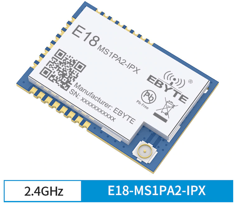
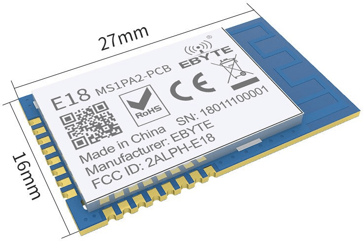
OwnerE18-MS1PA2, E18-MS1PA2-IPX, E18-2G4Z27SI or E18-TBH-27 USB Test Board are new boards from EBYTE with the CC2530 chip. The manufacturer promises better technical parameters but hides the real name of PA (power amplifier) even if you remove the cover shield from the board.
The existing documentation from the manufacturer instructs to compile a firmware with the HAL_PA_LNA flag. The same flag is used with the old and well-known CC2591 PA. But the board uses different pins to control PA and LNA. Therefore, the standard firmware for CC2530+CC2591 chips does not work.
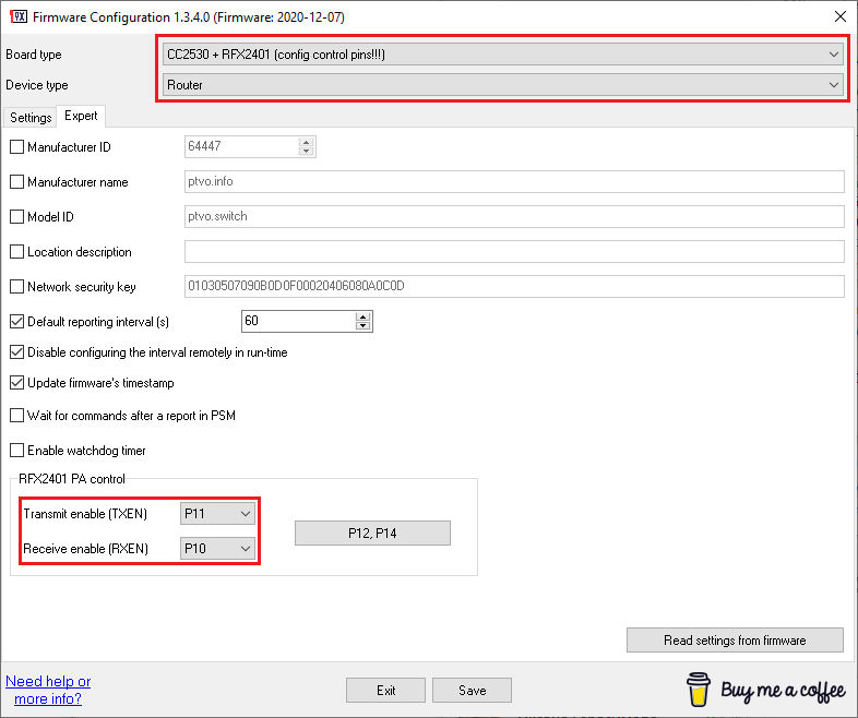
The configurable firmware allows you to avoid this problem. It can create the necessary firmware for you. You should use the following settings to prepare a router firmware for that board. Of course, you may use other features to the firmware, like a status LED indicator.
Nirm
Can the P0.7 pin of E18-MS1PA2 be used freely by us to use it as GPIO (and it is not used for PA purposes)?
As far as I know, the past model E18-MS1PA1 used three pins, specifically PIN1.1, PIN1.0, and P0.7, for PA Control.
Owner
Yes, you can use this pin in your configuration.
Matthias
Hello. Can the firmware handle the Ebyte E180 ZG120A boards?
Marius
Hello, I have an E18-MS1PA2 USB test board and I want to connect to mhz19b via RX/TX. On which pin? Pin 0.2 and 0.3 do not work.
Owner
P02 and P03 are correct. Please try to swap these pins.
Marius
unfortunately without success when turning the contacts.
my settings:
Board type: CC2530 + RFX2401 (config control pins!!!)
Device type: Router
Transmit enable (TEN): P11, Receive enable (REN) : P10
Model ID: ptvo airsense
Update firmware’s timestamp : 2023-08-06
Set default reporting interval (s): 60
Output pins:
P02: Output 2, MHZ 19 (Address (dec): 1)
P05: Output 4, GPIO, Pull-up (Role: Generic)
P17: Output 5, GPIO, Pull-up (Role: Generic)
P16: Output 6, Temperature sensor (1-wire), External pull-up (Type: DHT11)
Input pins:
P20: Input 1, External wake-up, Pull-up
P21: Input 5, GPIO, Pull-up, Switch, Toggle, Link to out 5 (Bind command: On/Off)
this comes on zigbee2mqtt Log:
Publish ‘get’ ‘l2’ to ‘0x00124b002724215b’ failed: ‘Error: Read 0x00124b002724215b/2 genAnalogInput([“presentValue”,”description”], {“sendWhen”:”immediate”,”timeout”:10000,”disableResponse”:false,”disableRecovery”:false,”disableDefaultResponse”:true,”direction”:0,”srcEndpoint”:null,”reservedBits”:0,”manufacturerCode”:null,”transactionSequenceNumber”:null,”writeUndiv”:false}) failed (Status ‘UNSUP_CLUSTER_COMMAND’)’
I’ve also tried it out by only setting CC2530 as the board type. Unfortunately without success
shay
Hi,
is there a way to control the transmit power of the module?
Thanks
Owner
Yes, it is possible in the Premium version of the configurable firmware.
shay
can you please tell me how?
Owner
Please look here
https://ptvo.info/zigbee-configurable-firmware-features/rf-signal-level-control/
Никита
Hello. Is it possible to put E18 ms1pa2 instead of ms1pa1 on the board of the 8-channel relay MODKAM? if so, what settings in the firmware to change? Thanks!
Owner
Yes, you can use E18 ms1pa2 too.
https://ptvo.info/zigbee-configurable-firmware-features/e18-ms1pa2-ipx/
Frans Hettinga
If you don’t setup RXEN and TXEN on a MS1PA2-PCB(Just select CC2530 as Board type), can you use P10 and P11 for other purposes (like external sensor power control)?
Owner
These pins are always connected to a power amplifier. I think you can get unexpected behavior.
Frans
So on these boards you can’t use external sensor power control?
Owner
Yes, you cannot do it. Also, you cannot create a battery-powered device with it.
Err
Why can’t one create a battery-powered device with the MS1PA2-PCB, is it because it consume too much power?
Owner
Yes, correct. This chip consumes about 90 mA when it sends data to a coordinator.
Jirm
Hi. I setup a router based on E18-TBH-27 USB Test Board (eByte E18-2G4Z27SI). All goes fine to flash, but once setup I have some questions:
I´m using Zigbee2Mqtt (Z2M) as zigbee net manager (trough HA Addon) and have a issue because router seems it´s not reporting periodically.
First join to zigbee net and device setup in Z2M was smoth and nice once flashing device with this awesome Firmware Configuration 1.3.6.0. (Firmware: 2021-01-14).
Zigbee net join is done but once this, no more reportings comes from router.
The router function itself seems working propperly and devices attached with it I see mantain reporting propperly trough time, so I suspect that is only mather about the periodic reporting configured on router.
I setup exactly same configuration is showing here on upper image from firmware configuration (Expert tab – Settings tab have all disabled) , and check enabled for Default reporting interval (s) : 60
Other problem I noticed, I cannot manage to build a only router function with disabled all end device attributes, so all propieties seems enabled like switch, click, action, humidity , temperatre, voltage, etc… associated to it and declared over mqtt and I tryed several times to configure over FirmwareConfiguration software without luck .
We have any chance to build a router firmware, but only with this function ?
Best regards
Owner
Hi,
1. Enable one output on any unused pin for periodic reports (otherwise, nothing to report).
2. Change ModelId to “lumi.router” (w/o quotes) on the Expert tab.
Giovanni+C
hello, any chance to have a coordinator firmware with correct pins to use the PA correctly?
Owner
Sorry, but I cannot make that firmware.
Giovanni C
do you have any link where I can find it ?
Sandr
Can i use not PWM ports for TXEN / RXEN?
I need 4 hardware PWM out….
Owner
Hi. TXEN and RXEN depend on a power amplifier. PWM also uses a fixed pin number. It is possible; you may find a variant where TXEN/RXEN and PWM may co-exist.
Sandr
Based on your info? HW PWM can be set on next pins^
PWM #1 pins: P13 or P16
PWM #2 pins: P10 or P20
PWM #3 pins: P14 or P17
PWM #4 pins: P11 or P23
And what you can reccomend configuration?
What about:
PWM #1 pin: P13
PWM #2 pin: P20
PWM #3 pin: P14
PWM #4 pin: P23
TXEN pin: P11
RXEN pin: p10
Alexey
Thanks for the quick response, I correctly understood that pins 11 and 10 cannot be used.
Owner
If a power amplifier on your board uses these pins, you cannot use these pins for other purposes.
Alexey
Hello. Sorry in advance for my English (I am Russian speaking).
Question about RFS 2401 control, for the maximum signal, should I send a logical unit to pins 11 and 10? or there is nothing to do, everything will work well?
Owner
Hello. The firmware sets the maximum power signal programmatically. Pins are used to enabling the power amplifier.