 Owner
OwnerHow to select a CC2530 board
eBay and Aliexpress offer several boards with the CC2530 chip (keyword: CC2530). You may select any board, but use the following criteria:
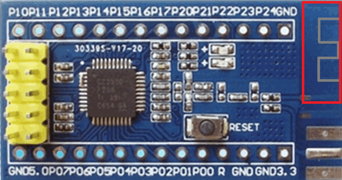
- The board must have the CC2530F256 chip (fig. 3). The key number here is 256, and it means 256 KB of flash memory. Most firmware was compiled for 256K memory.
- The board may have many pins or contacts. If you do not have a soldering iron, then select a board with headers. I would suggest choosing a board where each pin has the corresponding label. The label may slightly different on different boards: P0.2, P02, P0_2 are the same pin. The board must have at least the following pins:
- P0.2, P0.3, P2.0 – they are used for a UART interface. If you plan to use this board instead of CC2531 and connect to your SBC like Raspberry Pi, then you need these pins. If you upload a router firmware to this board, then these pins are optional.
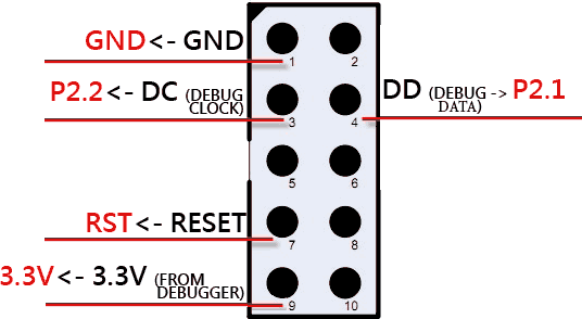
- P2.1, P2.2, RST – used for uploading firmware.
- GND – Ground.
- The power source (VCC) – it may be 3.3V, 5V, or both. This pin can be marked by VCC only. Internally, the CC2530 chip uses the 3.3V voltage, but a manufacturer may add a voltage regulator on the board, and you may use any supported voltage (3.3V or 5V, no difference). Please, read a board’s description carefully about the voltage.
- The board may include an additional small chip (fig.5). Most likely, this is a wireless signal amplifier. Usually these boards contain “Long-range”, “RF front-end”, “RF amplifier”, “CC2591”, “RXF2401” in a description. These boards require special firmware. I would suggest selecting this board if you really have a firmware for this combination of the main chip (CC2530) and the RF front-end chip.
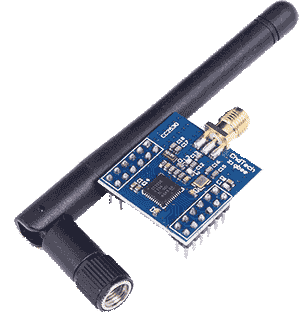
- The board may contain an antenna on-board (fig.2, 3, 6) or a connector for an external antenna (fig. 1, 3, 4, 5). The board with an external antenna will work better in most cases.
- Some boards may have a metallic shield over the main chip and/or the RF front-end. This shield protects the board from radio noises (good). But I would suggest buying this board from trusted vendors only because you cannot be sure about chips under this cover.
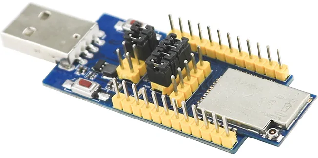
- Rare CC2530 based boards may include a USB interface (fig. 6). CC2530 does not have native USB support apart from CC2531. Therefore a manufacturer adds an additional chip on the board. The additional chip implements the USB interface and the CC debugger. Therefore you can upload firmware to this board without a special debugger (CC debugger or SmartRF04EB). Therefore it holds small space on your work table. It can be useful for developers. If you need only one CC2530 or CC2531 for a coordinator role, you may save money. Please, read the board’s description because the USB interface and chip may be used for another purpose. Therefore I cannot recommend this board for beginners.
 | My favorite: a board with a power amplifier and external antenna EBYTE E18-MS1PA1-IPX + breadboard for easy soldering and mounting + compact power supply (option 1 or option 2) + external antenna |
 | The compact board with an external antenna |
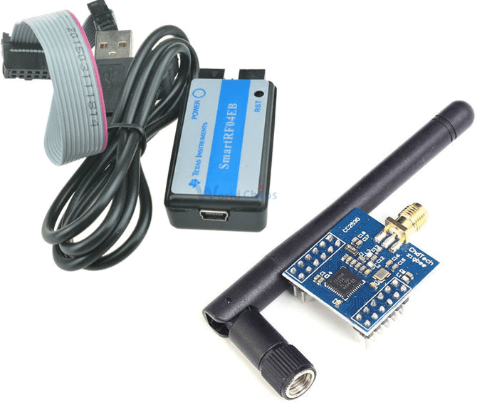 | CC2530 kit with flasher & debugger. |
 | The board with the internal antenna, place for an external antenna connector, and a debug interface header (compatible with the CC debugger cable, the DuPont cable is not required) |
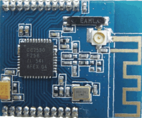 | The compact board with the internal ceramic antenna and an external antenna connector |
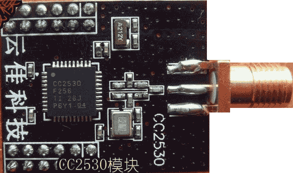 | The compact board with an external antenna. Black design. |
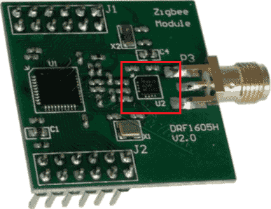 | The CC2530 board with the RF front-end |
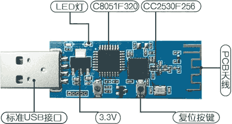 | Fig. 7 The CC2530 board with a USB connector and the additional 8051 chip |
Pre-requisites
Here is an example for the most simple case when all pins are soldered on the board and have labels (fig. 1).
- The CC2530 board.
- The DuPont cable (5 wires, female-female).
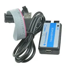
- The CC-debugger or SmartRF04EB (look very similar).
- The USB cable between the debugger and your computer (it usually comes with the debugger, USB-A <-> USB-mini).
- Computer with Windows.
- Flash Programmer V1 (V2 does not work).
How to connect CC2530 to the debugger
It is simple. Use the DuPont cable and connect pins on the debugger’s connector to the corresponding pin on your board.
Note: if CC-debugger cannot detect your board, additionally try to connect the pin #2 to 3.3V.
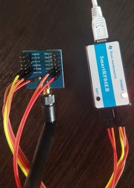
The board from fig. 2 is compatible with a flat white cable usually shipped with CC-debugger or SmartRF04EB. This flat cable can be connected to the yellow header (the red wire should be connected to pin #1 of this header).
Note: if your board has the 5V power pin only, then you must connect an external power source (5V and GND) to the corresponding pins on your board instead of 3.3V from the debugger. GND of the debugger and the power source must be connected at the same time.
How to connect a CC-debugger to your computer
Connect your debugger to a USB port on your computer using a standard USB cable. A new USB device should appear in Devices Manager on your computer. If you’ve installed Texas Instruments Flash Programmer before, the drivers for the new USB device will be installed automatically. You should see something like “SmartRF04EB” or “CC-debugger” in Devices Manager.
How to select a right firmware
Here are examples for general usage cases. All these examples may have exceptions.
- Select a firmware for the right chip: CC2530 in our case.
- If your board has an RF front-end chip, then you must select the firmware for a combination of the main chip and the RF chip (for example, CC2530 + RXF2401). For example, CC2530ZNP-Pro-Secure_LinkKeyJoin_RXF2401.hex
- Select a firmware for your Zigbee network. Devices with different network parameters are incompatible (they cannot communicate). Each Zigbee network has the following key parameters:
- Network Id (PanId).
- Security key.
- Radio channel number. This requirement is not strict. Many Zigbee devices may scan channels and find the correct channel number. But some Zigbee devices work with the pre-defined channel number only.
- Select a firmware for the device type you want to get from the CC2530 board:
- Coordinator: it should be connected to a computer or SBC (Raspberry Pi, BananaPi, OrangePi, etc.) because in most cases, it operates under the control of a computer. The firmware file name or description may contain keywords: “coordinator,” “ZNP.” For example, CC2530ZNP-Pro-Secure_LinkKeyJoin.hex. The ZNP firmware is universal because it operates under the control of a computer, and it may configure the board as necessary, probably for any Zigbee network.
- Router: it works independently (not linked to a computer) and extends coverage of your Zigbee network. For example, CC2530-router.hex.
You may download my firmware for a Xiaomi coordinator and router here.
How to flash (upload) firmware
Ok. You’ve connected the debugger and the board.
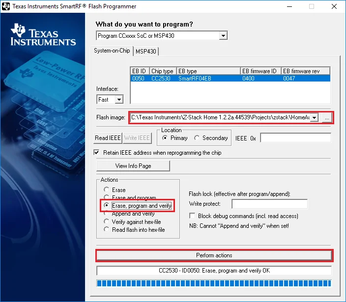
- Start Flash Programmer. Your debugger should be on the list. If the debugger does not appear there, try to press the “Reset” button on the debugger.
- Select a firmware file using the “…” button.
- Select the following options.
- Click the “Perform actions” button.
 Owner
Owner
Yang
Hi,
I’m trying to connect a BH1750 illuminance sensor using CC2530 to read its data and report it to CC2531 plugged into my computer. I have already flashed the firmware of CC2531 coordinator and set up mosquitto / zigbee2mqtt on my computer. How should I set its PANID and CHANNEL parameters in ptvo firmware software (as a beginner, the IAR development platform will make me more confused)
Owner
The device detects PanID and Channel automatically when it joins to your network. Of course, you should enable the join mode on your coordinator.
McMaciej
Hello,
Over the past few months (with some breaks), I’ve been working on creating my own “Light” that I can integrate into Home Assistant using a Sonoff Dongle 3.0. For the microcontroller, I chose the CC2530. My initial goal was simply to turn an LED on and off via Home Assistant. However, when I attempt to search for devices in Home Assistant, it does not detect the CC2530 running the Sample Light project from Z-Stack 3.0.2.
I have ensured that the PAN ID and the communication channel are correctly configured and match between devices. Despite this, the CC2530 still isn’t being detected. I’ve consulted the Z-Stack documentation and made numerous attempts with help from ChatGPT, Copilot, and other resources, but I seem to be missing a crucial step.
Thanks in advance for any help you can provide.
Pawel
Hi.
Is possible flash ZT2S zigbee modul ?
Owner
Unfortunately, no. This module contains an unsupported chip.
Esa
Hi
This is awesome project, and I hope to be able to get some custom sensors done in the near future!
I already did some testing, and got data from cc2530 UART, but then something happened, the LED is only very dimly lit. The module is possible to flash though.
My biggest question mark is, that my SmartRF04EB clone is not shown in the Flash Programmer when SoC programming is selected, even though it’s visible in device manager (I’m also using USBDeview where it shows normally). It’s also shown in Flash Programmer in the EB application (USB) and I can re-flash the firmware.
Does anyone have any insight into this? I’ve googles a few days straight and can’t find anything.
I already ordered some CC programmers from ali if those works better.
Thanks in advance for any tips!
Kind regards, Esa
Owner
It looks like damaged cc2530 or a short circuit/broken wire somewhere in your schematic.
Jason
I accidently assigned P2.1 as an Input and didn’t notice until after I flashed the .hex. Now when I am trying to connect and re-flash with a correct .hex, the CC Debugger light stays red. I assume that is cuz there is a battle over the P2.1 pin. Is there any way to recover this unit?
Owner
No, these pins should work for flashing too. Try to erase the chip after pressing the Reset button. Then flash a new .hex file.
Jason
The device doesn’t show up in the list in the Flash Programmer and the light stays red on the CC Debugger, so I don’t have the option to Erase.
P
I have a zigbee module from texas instruments. It has CC2530 on it. I want to read the flash from the module but when I open the flash programmer I don’t see any device in the list. I have the module directly connected to a COM port on my PC. Couldn’t I read its flash without a debugger?
Owner
Yes, you cannot read flash without a debugger.
Damian
Hi, i’ve buyed recently cc2530 with cc debugger on aliexpress, using provided here link. I’ve received device with label SmartRF04EB and installed TI Flash programmer v1. After connecting all and usb to PC, it is detected as SmartRF04DD in device menager and Windows can’t find drivers for it… Googling without luck (almost all links for paid chinese downloads). Any one can provide driver for this device?
Owner
Could you please try the driver from the following page?
https://www.ti.com/tool/CC-DEBUGGER
Damian
Yes, i’ve tried. It doesn’t match… I’ve tried installing with installer inside archive and also tried to manually chose driver from device menager – it says that there is nor suitable driver…
Damian
Sorry, I’ve posted too fast – I’ve tried once more time to install manually and this time it worked! Maybe I’ve choosed wrong subdir last time…
Vadim
Hi! I’m using a SmartRF04EB to flash a CC2530 (E18-MS1-PCB). The LED on the SmartRF04EB is always red but the Flash Programmer says that it could program and verify correctly.
However when I connect the device to the MQTT server, it shows old Model ID and Manufacturer name, not the ones I entered. It also shows 5 switches in Home Assistant instead of just one I chose. 4 of them aren’t working though.
So basically it seems that the CC2530 was not flashed (I tried many times). But why then does the Flash Programmer say it could flash without any problems? I’m also confused by the always red LED, it seems like it shouldn’t be this way
Owner
Hi! The LED indicator should be red. Check your wires. Check that you’ve connected the Reset pin. Press, the reset button on SmartRF04EB.
Fahi
hi,
I’ve got cc2530 board(firgure 6, black one). I want to know is it possible to program this board without smartrf and just with cc debugger??? ( I don’t have soc)
Owner
Hi! CC debugger is enough too.
Alan
hi. This looks excellent. I’ve just flashed a cc2531 with zigbee2mqtt and I was wondering if I could use such a device to count S0 pulses from a smart meter. Looks like your Pulse Counter option is just what I need 🙂 Have you known anyone do this using your software and a cc2531?
From what I’ve read the S0 output statuses ON/OFF are defined via the current because the input voltage can be variable from 5v to 30v. This suggests some interface electronics.
Owner
Hi. Please, note that the configurable firmware does not support CC2531. I think this chip can work with firmware for CC2530, but I didn’t test it. Unfortunately, I’m a software engineer, my knowledge of electronics is very limited. I’m sure you can find the necessary shield board on Aliexpress. Something with optoisolated inputs and TTL outputs.
Alan
Thanks for your reply. Yes I would use a CC2530 for this S0 interface and I have sketched out an opto-isolated inputs and TTL outputs.
I also need to measure light levels. I see your firmware and the CC2530 supports Analog inputs. Could you please say what the firmware outputs and the range. e.g. is it the pin’s voltage (e.g. 0 – 3.3V) or a 0-100 range . Thank you
Owner
Please, look here:
https://ptvo.info/zigbee-configurable-firmware-features/
Jon Alexander Rogstad
Hi, I have the CC2530 Fig:6 and have successfully flashed it with “CC2530ZNP-Pro-Secure_LinkKeyJoin.hex” firmware via a TI CC Debugger.
But I can’t get it working with Home Assistant Zigbee2MQTT. Does anybody know if it would be possible?
Zigbee2MQTT log:
zigbee2mqtt:info 2020-02-29 14:09:35: Starting zigbee2mqtt version 1.11.0 (commit #unknown)
zigbee2mqtt:info 2020-02-29 14:09:35: Starting zigbee-herdsman…
zigbee2mqtt:error 2020-02-29 14:09:35: Error while starting zigbee-herdsman
zigbee2mqtt:error 2020-02-29 14:09:35: Failed to start zigbee
zigbee2mqtt:error 2020-02-29 14:09:35: Exiting…
zigbee2mqtt:error 2020-02-29 14:09:35: Error: Error while opening serialport ‘Error: Error: No such file or directory, cannot open /dev/ttyACM0’
The board:
https://www.aliexpress.com/item/4000112752493.html?spm=a2g0o.productlist.0.0.71c27ae2DKtTlH&algo_pvid=6061f56d-3ec0-4c17-8b56-ad0a94cbe706&algo_expid=6061f56d-3ec0-4c17-8b56-ad0a94cbe706-13&btsid=0be3764315829823098438192ec853&ws_ab_test=searchweb0_0,searchweb201602_,searchweb201603_
Owner
Hi,
You should change the COM port name in the z2m settings. ttyACM0 is for a USB stick. You need a port like ttyS1, ttyS2 .. ttySn
Jon Alexander Rogstad
Thanks, but it sadly didn’t work.
I tryed setting “port: /dev/null” and got the following message in the log:
zigbee2mqtt:error 2020-03-01 13:10:40: Error: Error while opening serialport ‘Error: Error: Not a tty setting custom baud rate of 115200’
Owner
You need a port like /dev/ttyS1, /dev/ttyS2 .. /dev/ttySn
Nothing else.
Moji
Hi Jon,
I had a same problem, I wonder if you solve it or not?
port must be /dev/ttyAMA0
and also choose UART for comunicate with cc2530, because UART is using by bluetooth by default.
Radoslav
Hi, I had successfully flashed CC2531, and it was working I have paired some device trough it, but from yesterday It can’t connect to network. Led is blinking every second, so it is trying to connect. I have already tried to repair with plugin and unplugging method, and even with button. Any other help, or should I just reflash it ?
Owner
I can only offer to reflash the stick. But it may break too (a RF transmitter part).
John
Maybe an addition to your description about connecting and flashing:
I also had some troubles flashing a CC2530+CC2591. The light stays mostly red but when it was green it complained about locked device/chip.
The solution was also connecting pin 2 of the CC debugger with the 3.3V pin 9 of the cc debugger (or the extra VCC pin on the CC2530 board.
Kalsan
Sounds very interesting! Could flashing also be achieved using an Arduino, as described for the CC2531 in https://www.zigbee2mqtt.io/information/alternative_flashing_methods.html ?
Owner
Yes, of course.
Radoslav
Hi,
do you support this E18-2G4U04B device too ?
link: https://www.aliexpress.com/item/32977395088.html
datashet: http://www.ebyte.com/en/downpdf.aspx?spm=a2g0s.imconversation.0.0.3ac63e5f8vl5Oq&id=523
do I need CC debugger to flash, or it is possible to flash it without it ?
Owner
Yes, you need the debugger. Also, you may use alternative flashing methods.
https://www.zigbee2mqtt.io/information/alternative_flashing_methods.html
You’ll need to unassemble this stick and solder wires to pad holes on it.
Maan Sulaimani
Hi
I have the CC591+CC530 board I think
(fig1)
I use it as a Zigbee2MQTT
Extended Router
(Not main router)
I was able to flash it
But there no indicator LEDS and no button
I there a way to wire some ?
+ how do I connect the extender to main router ? … and how do I know that it’s connected
Also you say something about a PAN ID and a key
…
How can I configure these ?
Owner
Hi,
1. Look at the following configurable firmware. You may enable the status LED on any pin.
https://ptvo.info/zigbee-switch-configurable-firmware-router-199/
2. The router should connect automatically to first network opened for joining.
LetraGis
Hi, how can I flash the CC2530 with RF front-end and external antenna with RaspberryPi? Here https://www.zigbee2mqtt.io/information/alternative_flashing_methods.html is shown how to flash CC2531 with it, but Im not so sure about the wiring.
Owner
Every CC2530 board has the following pins:
GND or G –> pin 39 (GND)
RES or RST or R (reset) –> pin 35 (GPIO24, BCM19)
P22 (DC) –> pin 36 (GPIO27, BCM16)
P21 (DD) –> pin 38 (GPIO28, BCM20)
Pedro Almeida
Hi Jean. Could you please, tell me which faulty jumper was? I had the same problem and i cannot resolve :(!
Owner
I think it was a problem with assembly (for example, a soldering stain).
Jean-Francois Couture
Hi, I have a couple of CC2530 ( fig. 1) and flashed them without any problems and works. Now, I would like to update the firmware on them but the CC debugger led’s stays red and the flash program is unable to see them. They do work if I connect them back to my Rpi and zigbee2mqtt. Any reason i’m not able to flash them a second time ?
I did connect to p2.2, p2.1, rst, gnd and 3.3V. I even tried bridging pins 2 and 9 on the debugger (thats how it worked for me the first time).
thanks,
J-F
Owner
Hi, try to press the “Reset” button on the CC debugger.
Jean-Francois Couture
I did multiple times and the leds still stays red. Any other ideas why the debugger is failling to see them ?
Thanks
Jean-Francois Couture
Ok, so, Forget what I just wrote. I found the problem 🙂
Turns out that it’s a faulty jumper wire that’s the culprate. now the led is green and i’m all good to go !
antst
What do you think about this idea?
https://github.com/Koenkk/Z-Stack-firmware/issues/70
Do you think it is feasible to implement this on top of router firmware?
Owner
I think it is too hard.
Breno
Hi,
I have a CC2530 ChdTech (The same from the tutorial). But, i do not have any cc debugger. Is there any way to configure the CC2530 or check the firmware without the CC debugger?
Owner
You need the debugger or use the alternative method:
https://www.zigbee2mqtt.io/information/alternative_flashing_methods.html
Mike Stewart
Hi when i plug the cc2530 compact board with external antenna into the cc debugger the red light on the cc debugger turns off and I get the usb device disconnected sound in windows.
It happens on connecting 3.3V and GND from the CC_Debugger CC2530.
Is this a faulty cc2530 board?
With all the wires connected and pressing reset on the cc debugger, nothing happens.
Owner
It looks like a short circuit in your wiring…
Filip
Did you manage to solve this problem? I am experiencing exactly the same thing with my cc2530 (fig. 3).
I flashed cc2530 with antenna without a problem. This one do not work for some reason..
Owner
The most simple way is to re-flash the router.
Bastian
Hi,
is there an other way than re-flashing the router?
Greetings
Bastian
Bastian
Hi,
how can I rejoin a router (cc2530) if it was already joined to another zigbee network?
Greetings
Bastian
Kevo
Do you know if the cc2530 modules (with out USB) can be made to work with the Raspberry Pi over the SPI bus. If so has there been any tutorials?
Owner
Hi,
I didn’t see standard CC2530 boards with the SPI bus interface. Why UART is bad?
Michel
Hi,
I got the CC2530 as shown in your Fig. 2 “The board with the internal antenna, place for an external antenna connector and a debug interface header”.
I have connected this to the black TI CC debugger interface which I have successfully used before to flash a USB CC2530 variant, using the original flat cable that comes with the debugger.
The CC2530 board lights up. A steady red LED and a small blue blinking LED.
When I start the TI smart RF flash programmer software v. 1.12.8, and select “programm CCxxx SoC or MSP430” the “system on chip” window stays empty, so I can programm. Any idea on how to solve the issue?
Owner
Hi,
Try to press the “Reset” button the debugger several times.