To add a 2-wire (I2C) temperature or environmental sensor, you should select any pin, select the “Temperature (2-wire)” sensor type, and select a subtype (e.g., BMx280), specify the I2C address of the sensor as a decimal number. On the next row (Output2 in this example), you should define a I2C clock pin.
First of all, you must specify a pin for a sensor. It is the SDA pin. Then it would help if you defined the SCL pin. For example, output 4 – BME280, and output 5 – I2C SCL.
I2C configuration for a sensor
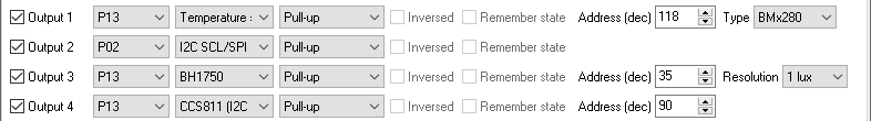
If you connect several sensors on one bus (pin), you may define the SCL pin only once.
I2C configuration for sensors on one bus
Zigbee: Accepts the “read” and “write” commands on the endpoint for the SDA pin.
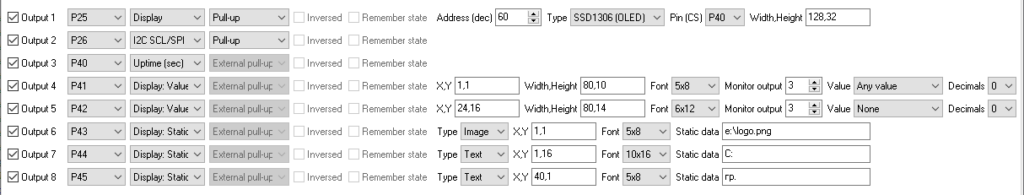
When building your own DIY Zigbee devices, incorporating a display can significantly enhance their functionality and user experience. From simple 7-segment LED indicators to more advanced LCD or OLED screens, displays provide a practical and visually appealing way to interact with your Zigbee device. This article will explore the various types of displays you can use, their compatibility with Zigbee-based projects, and tips for integrating them seamlessly into your DIY designs.
The SGP40 is a digital gas sensor designed for indoor air quality monitoring by measuring volatile organic compounds (VOCs). Key features include long-term stability, low-power consumption, and an I²C interface for easy integration with microcontrollers.
⚠️ THIS FEATURE IS AVAILABLE ON CC2652 or CC1352 CHIPS ONLY
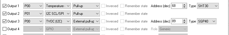
SGP40 sensor with temperature and humidity from SHT30 on one bus
The SGP40 sensor (Buy on AliExpress #1, #2) requires environmental temperature and humidity for better results. The example above shows that two I2C sensors are connected on the same bus. SHT30 provides the necessary data. It should be defined first in the configuration (above) in the configuration. You could also use separate sensors for temperature and humidity in the same manner.
The firmware converts the raw value from the sensors to the VOC index value in the range from 0 to 400 and reports it as an analog value.
0-100
Excellent
No measures needed
100-200
Good
No measures needed
200-300
Lightly Polluted
Ventilation suggested
300-400
Moderately Polluted
Increase ventilation with clean air
400-500
Heavily Polluted
Optimize ventilation
A home automation system can also send temperature and humidity instead of built-in sensors. You should send it as a single precision float in the analog input value cluster.
Analog value: 65NNN where NNN is a humidity value, for example, 65050 for 50%. Humidity range: 0 … 100. Analog value: 64NNN where NNN is a temperature value, shifted by 25. For example, 64000 for -25C, 64025 for 0C, 64050 for 25C. Temperature range: -25 … 100.
write - set the temperature value 25C.
Topic: zigbee2mqtt/[friedly_name]/set
Payload: {"[channel]": 64050}
Channel: l1, l2, l3 … l16
write - set the humidity value 50%.
Topic: zigbee2mqtt/[friedly_name]/set
Payload: {"[channel]": 65050}
Channel: l1, l2, l3 … l16
The INA226 is a high-side current shunt and power monitor with an I2C interface. These sensors offer high accuracy for current and voltage measurements in various applications. With its integrated ADC, the INA226 can measure bus voltages from 0V to 36V and shunt voltages with a common-mode voltage range. It provides programmable conversion times and averaging, making it versatile for different precision requirements.
The INA219 is a simpler device suitable for basic current sensing applications, while the INA226 offers higher precision and additional features such as integrated voltage reference and programmable alert functions. The INA226 is ideal for more demanding applications that require precise current measurement and advanced monitoring capabilities.
INA3221 offers a 3-channel monitoring module.
INA sensors are I2C-compatible and commonly used in power management systems, battery chargers, and various industrial applications where accurate current and voltage measurements are essential for monitoring and control purposes.
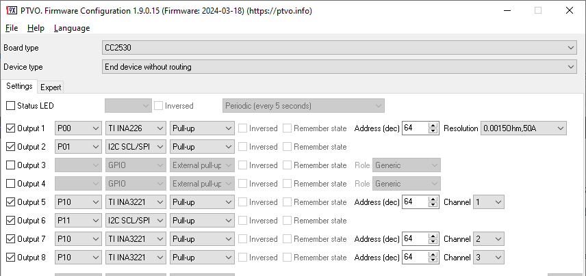
INA sensor configuration example
INA219 resolution – this option allows you to select a measurement voltage and current range (wider range – less accuracy).
INA226 resolution – this option depends on a used shunt resistor with your sensor or sensor board (less current – higher accuracy). Please note that the firmware does not support other nominal values for shunt resistors.
The X9C102, X9C103, X9C104, X9C503 are digitally controlled (XDCP) potentiometers. The device consists of a resistor array, wiper switches, a control section, and nonvolatile memory. The wiper position is controlled by a three-wire interface.
⚠️ THIS FEATURE IS AVAILABLE ON CC2652 or CC1352 CHIPS ONLY
X9C103S – digital potentiometer
Connecting X9C10X to a Zigbee module
From X9C10X to a Zigbee module: GND: connected to GND on a Zigbee module. CS (chip select): Connected to any pin configured as X9C100 (P00 – DIO0, see below). INC (increment): Connected to any pin configured as I2C SCL/SPI CLK (e.g., P02 – DIO2). U/D (up/down): : Connected to any pin configured as an additional parameter (e.g., P04 – DIO4). VCC: Connected to 3.3V.
Firmware configuration
Firmware configuration
Remember state – if this option is active, the firmware remembers the last level and restores it after power up. Otherwise, the firmware sets the maximum resistance on the X9C10X output (VL – VW). Pin (Up/Down) – it is the “U/D” pin. It has the same pull-up resistor settings as the master output pin. Transition time (ms) – if this interval is not zero, the firmware smoothly changes the output resistance between two states. Linked input – the mode of the linked input that controls this output.
Zigbee commands
The device acts as a level control device. You can change the level from 0 to 255, and the firmware scales it to 0 – 99 levels in X9C10X. When you set the zero level in Zigbee, the firmware forcibly makes 99 steps down. It allows synchronizing levels between the device and Zigbee. In other cases, the firmware calculates a difference and makes the necessary number of steps up or down.
on/off - The "Off" command sets the minimum level, and the "On" command restores the last level (before off). Look for commands and examples for GPIO outputs.
write - sets the level.
Topic: zigbee2mqtt/[friedly_name]/[channel]/set/brightness
Channel: l1, l2, l3 … l16
Payload: value (0 - 255)
Topic: zigbee2mqtt/[friedly_name]/set/[channel]
Channel: l1, l2, l3 … l16
Payload: {"brightness": value, "transition": 3}
value - 0 - 255.
transition - (optional) the transition time in seconds between states.
read - reads the current value
Topic: zigbee2mqtt/[friedly_name]/[channel]/get/brightness
Payload: none
Returns: {"brightness_[channel]": value}
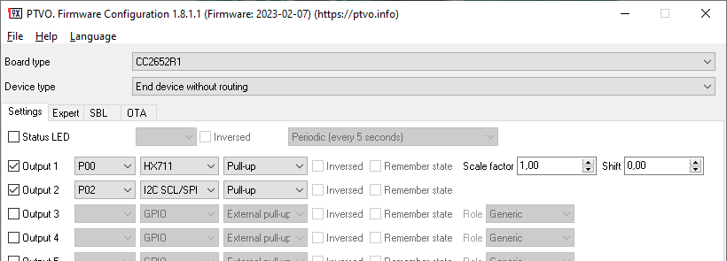
The HX711 Load Cell Amplifier is a module that is used to take the signal coming from your load cell and convert it into a digital signal that your Zigbee-compatible chip can take and process.
⚠️ THIS FEATURE IS AVAILABLE ON CC2652 or CC1352 CHIPS ONLY
Connecting HX711 and Load Cell to a Zigbee module
From Load Cell to HX711: Red wire: E+ on HX711 White wire: A- Black wire: E- Green wire: A+
Load Cell
HX711 module
From HX711 to a Zigbee module: GND: connected to GND on a Zigbee module. DT (data): Connected to any pin configured as HX711 (P00 – DIO0, see below). SCK: Connected to any pin configured as I2C SCL/SPI CLK (e.g., P02 – DIO2). VCC: Connected to 3.3V.
Firmware configuration
Zigbee’s firmware settings
Scale factor – allows you to convert a raw sensor’s value to a weight value.
Shift – allows you to calibrate a zero offset (tare weight).
Calibration
Assemble your Zigbee device (connect a load cell, power, etc.).
Configure and upload the firmware with “Scale factor” = 1.0 and “Shift” = 0.
Save a custom converter for your device (on the Experts tab) and add it to your Z2M.
Join your device to your Zigbee network.
Remove any weight from your load cell.
You should start receiving raw measurement data. It is the shift value (tare weight). Write it down somewhere. Then you can enable the “Enable zero calibration” switch in Z2M, and the device will remember this value in NVRAM.
Place any known weight on your load cell (you can find several tutorials about this on Google).
You should receive a new raw value for the measured weight.
Calculate a scale factor: (Measured value – Zero value) / Weight (kilograms or pounds).
Type the scale factor in the corresponding field in Z2M and press Enter. The device will remember this value in NVRAM.
Finally, you can update these constants in the firmware and re-flash it. In this case, you do need to make a new calibration when you reset a device to the factory defaults.
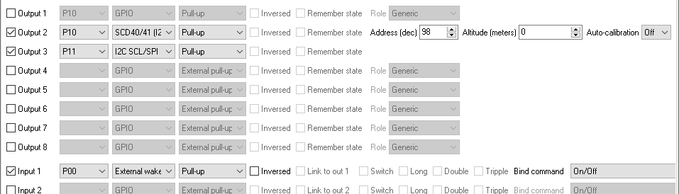
The SCD40 is a compact CO2 sensor that provides accurate carbon dioxide (CO2) measurements along with temperature and relative humidity readings. Key features include its small form factor, low-power consumption. It I2C- compatible sensor where you should configure the SDA and SCL pins, and define the sensor I2C address (see an example below). Of course, you can have different pins in your setup.
If your device is configured for power saving, the sensor measures all values only once when the firmware sends a periodic report. Please note, that every measurement takes about 6 seconds.
Otherwise, the sensor measures all values periodically every 5 seconds, but the firmware sends measured values with periodic reports.
⚠️ THIS FEATURE IS AVAILABLE ON CC2652 or CC1352 CHIPS ONLY
SCD40/41 configuration example
Additional parameters
Altitude – altitude over a sea level of your location for precise results.
Auto-calibration – the sensor will self-calibrate every several hours if you enabled this option.
Zigbee commands
You may send some sensor-specific commands to your higher-level system. You should write the necessary command single precision value to the “Analog input” cluster.
63000 – factory reset. 63001 – sensor restart (re-init). 63002 – start self testing. It takes about 10 seconds. 63900 – 64100 – set a temperature offset (64000 + offset value, so, the offset can be positive or negative). By default, the sensor has the temperature offset of 4 °C. If you see that the sensor measures a wrong temperature value, you can change this offset (note, this is an environment’s temperature). 65000 – 66100 – set the ambient pressure in kPa (65000 + pressure value). The maximum pressure value is 1100 kPa.
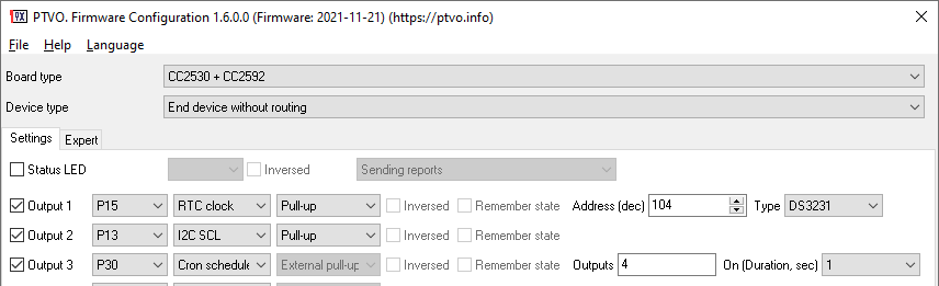
The firmware supports the most popular RTC chips like DS3231 and DS1307. These battery-powered chips can count time independently with the main module. The firmware reads the time from these chips at the boot time and periodically synchronizes the module’s time with RTC.
RTC chips support the I2C protocol. Therefore, you can add them in a similar way, like other I2C sensors.
⚠️ THIS FEATURE IS NOT AVAILABLE IN THE CC2530/CC2531 ROUTER FIRMWARE
RTC clock setup
Zigbee internals
Zigbee cluster: ZCL_CLUSTER_ID_GEN_TIME Zigbee attributes: ATTRID_TIME_TIME (UTC data type, 32-bit number of seconds since Jan 1, 2000) Zigbee commands: read, write.
Zigbee2MQTT commands
You should create a custom converter for your device, place it in the “data” folder, and add it to the configuration.
read - immediately reads the current time.
Topic: zigbee2mqtt/[friedly_name]/get/[channel]
Channel: l1, l2, l3 … l16
Payload: 1
Returns: The counter value {"[channel]": float_value}
write - this command allows you to synchronize time with the host. It is not recommended to call it directly because the device expects an encoded value. The custom converter gets the current host's time and calculates the correct value automatically.
Command example:
const values = {timeStatus: 3, time: time};
endpoint.write('genTime', values);
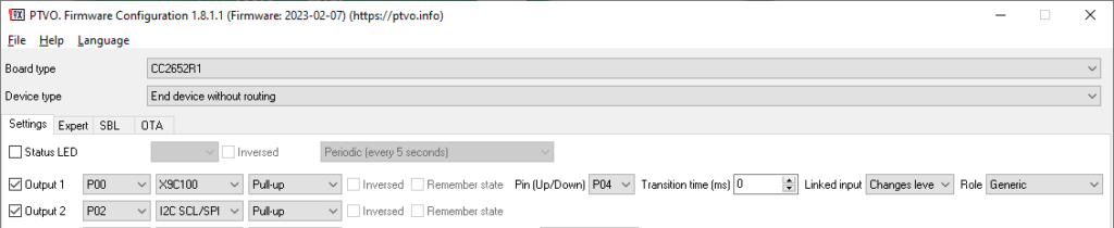
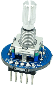
A rotary encoder is a type of position sensor used to determine the angular position of a rotating shaft. It generates an electrical signal, either analog or digital, according to the rotational movement (more info).
Digital rotary encoder
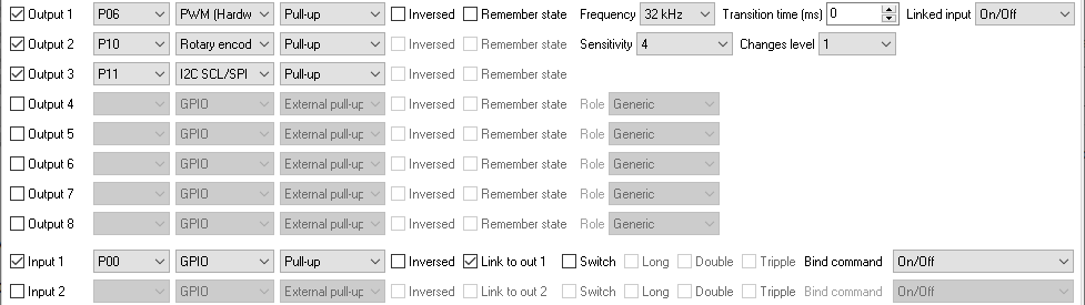
The firmware counts impulses in the 500 ms interval and sends a positive value for CW rotations and a negative value for CCW rotations. Optionally, the firmware can handle and send an event for a click button.
The image above is an example. You can connect “Output 1” and “Output 2” signals to any available pins. The “I2C SCL” line should be defined immediately after the “Rotary encoder” sensor.
Note: Output and input pins are not relevant for sensors. You can also configure your rotary in input pins, but without additional options.
Changes level – this option allows you to link the rotary encoder to a PWM or LED output and control PWM signal width or brightness level up or down.
Sensitivity – this option is used when with the previous option and changes a step size per each tick.
If your encoder has the additional push button, you can connect it to an input, and it will toggle a linked output state.
 Owner
Owner