 Owner
OwnerThis firmware allows you to create a Zigbee switch device with a flexible configuration of inputs and outputs. I’ve created a base firmware for CC2530, CC2530 + CC2590 , CC2530 + CC2591 and CC2530 + CC2592 chips. The attached configurator for Windows can write your device configuration to the selected base firmware. Then you can save the customized version to a separate HEX file and upload it to your device.
Inputs and outputs can work independently. So you may create a switch without a control button, or a simple button only.
The device with this firmware also works as a router.
Note: the firmware is designed for constantly powered devices.
Options
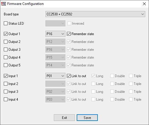
Remember state – The firmware saves the output state to NVRAM and restores it after power off/on.
Link – The input immediately controls the state of the corresponding output. The device sends the on/off state of the output to a coordinator. Otherwise, the input is independent.
Long – The firmware detects and reports to the coordinator a long click (2000 ms).
Double – The firmware detects and reports a double click (max 500 ms between clicks).
Triple – The firmware detects and reports triple-click (max 500 ms between clicks).
Zigbee internals
- The firmware creates a separate endpoint (1..5) for every configured output and/or input (max 5 endpoints).
- The firmware reports the state of an independent button via the “ZCL_CLUSTER_ID_GEN_MULTISTATE_INPUT_BASIC” cluster and the “PRESENT_VALUE” attribute. 1 – single click.
2 – double click.
3 – triple-click.
4 – long click. - The firmware does not send a separate report for the linked button. Otherwise, it sends reports about the output state via the “ZCL_CLUSTER_ID_GEN_ON_OFF” cluster and the “ON_OFF” attribute.
- You may control the output state via the “ZCL_CLUSTER_ID_GEN_ON_OFF” cluster and the “ON_OFF” attribute.
- The “ZCL_CLUSTER_ID_GEN_ON_OFF” cluster also accepts the “read”, “configure” and “onOffWithTimedOff” commands: “read” – returns the current state on the specified endpoint.
“configure” – set the periodic reporting interval for the output. The “minReportInt ” attribute specifies the reporting interval in seconds. If “minReportInt ” is 65535, the firmware disables periodic reports. “onOffWithTimedOff” – sets the output state to “HIGH” for “onTime” milliseconds, and automatically resets to “LOW”.
Updates
2020-04-01 Released v2.
2019-08-14: Fixed bug with 3rd and 4th inputs.
2019-06-27: First release.
 Owner
Owner
Gerben
hello,
I make a watermeter sensor.
is it possible that it writes the value to memory and when home assistant comes online it read out the latest value?
because now when I take water and home assistant is booting up then it will miss some pulses.
better is that the sensor counts the pulses without home assistant and that home assistant read that.
Owner
I think, it is useless in most cases because a measured value can be obsolete at that moment and can give you a wrong representation of the current system status.
ConductiveInsulation
How exactly am i supposed to flash this Firmware? Neither the Firmware created with this tool or any software I download for the cc2531 board i have is accepted because the Flash is apparently too small. I’ve tried a lot of different Firmwares but none of them worked. Below is the output of the cc-tool.
$ sudo cc-tool -e -w router-cc2531-std.hex -t
Programmer: CC Debugger
Target: CC2531
Device info:
Name: CC Debugger
Debugger ID: 1771
Version: 0x05CC
Revision: 0x0044
Target info:
Name: CC2531
Revision: 0x24
Internal ID: 0xB5
ID: 0x2531
Flash size: 128 KB
Flash page size: 2
RAM size: 8 KB
Lock data size: 16 B
Erasing flash…
Completed
Flash image size exceeding flash physical size, writing canceled…
Owner
Sorry, but all firmware are compiled for flash size 256 KB
ConductiveInsulation
Thank you, I was not aware that multiple versions of this chip exist.
Victor
Hi, Came here after seeing https://github.com/Koenkk/Z-Stack-firmware/issues/222
Installed this firmware on a cc2530 and pairing to my coordinator running on Z2Tasmota (on sonoff zigbee bridge) seems to work fine however, i don’t get periodic reports on tasmota console as i see for the one running the z-stack firmware. I see that the firmware is set to 60s reporting, but i get nothing on the console even after 15m.
However, i felt the router might actually be working since it responds when i do a map discovery on tasmota. How do i get periodic mqtt notifications every 60 secs confirming that the router is functional?
I am not using Z2MQTT due to instability with the tasmotized Sonoff zbbridge in ZHA. The device gets laggy and unresponsive after a few days. Guess there might be a problem with the tcp server running in the ZHA mode. Saw this problem both when using ZHA integration directly on HA and also when using Z2MQTT making a connection from a docker container.
Owner
Hi, I’m not sure that Z2Tasmote supports PTVO firmware.
Victor
Ok, i did end up adding the ptvo router to my zb network and it is doing all the routing functions normally… Just that i don’t get any notifications about the ptvo routers health at all on tasmota console apart from when it was paired or when i do a zb map refresh. So, i wont know if it is dead unless i realize that my motion sensors connecting via this router haven’t responded for a while.
Overall, seems to serve my purpose of routing without spamming. Would have liked it to send a mqtt notification once in a while to just ensure that it is still alive but i guess the total silence is way better than the 1 sec spam that the z stack firmware has been sending out.
One bit that is surprising or something i don’t understand is that, with the zstack firmware and Z2MQtt, mqtt notifications only arrive once every minute. It’s only with Z2Tasmota that the zstack router sends status every sec and tasmota converts it to mqtt and makes it very spammy…
not sure how the internals works etc. so don’t know what’s going on.
Larey
Hey,
is this firmware also compatible for a battery power supply? like a cr2032 or a 18650 battery?
Owner
No, yet.
Larey
does it work?
But the battery will run out quickly or not
Owner
I’ve added the power saving mode to the Premium version.
https://ptvo.info/zigbee-configurable-firmware-features/power-saving-mode/
Tomas
I just learned about your firmware and it seems really great! Impressive work indeed!
Now to my question: Is there any feature that allows for basic logic like “if-then” to be locally executed? I am thinking about making a zigbee-version of my current wifi-based irrigation system (built on Wemos D1 mini) but I would then like to have a local fail-safe mode like “if link to coordinator lost – then close all valves (by switching the relays)”. Thanks!
Owner
Hi,
No, the firmware does not allow do it. For your irrigation system, you may open valves for a short interval using the trigger command. Then the firmware will close it automatically, even if a coordinator is offline.
Tomas
Ok, so I would then use the trigger command to open the valve and set the trigger time to a value that is a bit longer than I would normally use for irrigation, say 60 min. To close the the valve before the 60 min have passed, I could then use the on/off command? Is this correctly understood?
Is it possible to inverse the HIGH/LOW function of the trigger command (say if my relays happen to be low trigger)?
Thanks again!
Tomas
For automated irrigation with known irrigation times, I could perhaps use only the trigger command, i.e. send the “open valve command” and the wanted time at once (no need for a shut off command)?
Owner
The trigger command executes ON and OFF commands internally in a device.
Owner
You may call the trigger command with the precise interval and forget. Also, you may send the OFF command too. But if you send the ON command before the trigger is completed, the firmware will automatically OFF the valve when the trigger is finished. You may inverse the logic of on output for all commands.
Tomas
That would off course work as intended! Sorry for not getting it at first. Thanks a lot. I have a spare cc2530+cc2590 module doing nothing. I can’t wait to give this a try!
Dmitry
Am I can somehow use all 16 gpio as inputs? Or are you planned to create similar firmware?
Owner
Hi! Sorry. You cannot do it. Also, I didn’t plan to implement this configuration.
Emmanuel_FR
Hi,
I tried today to make my custom firmware : it just took me the time to wire, to find the netword key in hex, generate the firmware and… voilà !!! One minute later, I had a switch on Domoticz and was able to check that indeed I could output a logical signal. The only problem I had was to cycle the power and remove the CC-Debugger connections before pairing (not sure it was necessary…).
This is so great, many many thanks for this excellent work !! Do you have a Paypal accound to pay you a virtual beer?
Cheers !
Saeid
Hi,
Thanks for the great work. I just flashed a simple switch and usual ON/OFF and reading status works just fine.
By I cannot make the onOffWithTimedOff feature to work.
This and some other guesses did not work:
mosquitto_pub -t zigbee2mqtt/0x00124b000ef0b755/l1/onOffWithTimedOff -m 1000
I was not able to find any example of using the TimedOut feature anywhere on the web or in this blog.
Is onOffWithTimedOff supported by Zigbee2mqtt? If yes how it can be exploited?
If not shall I try to create a pull request?
Owner
Sorry, but the firmware does not this command.
saeid
Which firmware do you exactly mean?
The generated firmware created by this tool.
If yes what does this mean in the readme file:
The “ZCL_CLUSTER_ID_GEN_ON_OFF” cluster also accepts the “read”, “configure” and “onOffWithTimedOff” commands: “read” – returns the current state on the specified endpoint.
“configure” – set the periodic reporting interval for the output. The “minReportInt” attribute specifies the reporting interval in seconds. If “minReportInt” is 65535, the firmware disables periodic reports. “onOffWithTimedOff” – sets the output state to “HIGH” for “onTime” milliseconds, and automatically resets to “LOW”.
Owner
Oh yes, I’ve forgotten about this feature. Z2M has the corresponding “trigger” command for it (https://ptvo.info/zigbee-configurable-firmware-features/)
Elias Pereira
Friends, can anyone tell me how to disable the GPIOs that are not being used?
They are already unchecked in PTVO firmware configuration, but still appear in zigbee2mqtt.
Owner
You can create a custom converter for your device in the configuration and add it to Z2M.
Shah
Hi,
The sensor works just fine, in an attempt to make it more reliable I have enabled watchdog setting in the firmware builder.
I find that the sensor stops communicating sometimes with coordinator (Zigbee2mqtt), however the link led still blinks as if it is connected- and once it is power cycled it reconnects. ( I am not sure if this issue is from coordicator side or the sensor itself other sensors work when some fail) Is the watchdog timer set to reboot the device? or re-attemp connection to co-oordinator after connection failure?. Can LED change its status again once it looses connection? On a separate note:
Is it possible to select/define the network-ID as well with the network-key for dedicated networks? or it is a feature request?
Can the default re-set process be set to say more than 3 times power cycling say 5 times etc to make it more solid.
Thanks again for this wonderful tool that you have created Kudos for that, it has really separated programming layer away from its utility.
I hope/wish future releases would address some of these desired features?
Owner
Hi.
If LED blinks it means that the firmware is working. So, the watchdog timer works, or the firmware is stable :).
You may define network parameters on the “Expert” tab.
The number of cycles: some users cannot repeat 3 times, so 5 times is the impossible mission :-).
Saeid
Thanks. That was exactly what I was looking for
S. Shah
Hi, this was probably caused by flaky module, I changed the module and glad to know that all worked just fine as expected.
Here is the config that I used just FYI: when it was not working the GPIOS were tried with varius settings ( pull ups/down/tri) but the results were the same.
Board type: CC2530
Update firmware’s timestamp : 2020-06-16
Enable watch dog timer: Yes
Power saving mode (PSM): No
Status LED: Yes (Inversed)
Output pins:
P11: Output 1, GPIO, Pull-down, Remember state
P12: Output 2, GPIO, Pull-down
P13: Output 3, GPIO, Pull-down, Remember state
P14: Output 4, GPIO, Pull-down, Remember state
P15: Output 5, GPIO, Pull-down, Remember state
P16: Output 6, DS18B20, Pull-down (AA-BB-CC-DD-EE-FF-01-02)
Input pins:
P01: Input 1, GPIO, Pull-down, Link to out 1
P02: Input 2, GPIO, Pull-down, Switch, Link to out 2
P03: Input 3, GPIO, Pull-down, Switch, Link to out 3
P04: Input 4, GPIO, Pull-down, Switch, Link to out 4
P05: Input 5, GPIO, Pull-down, Switch, Link to out 5
S. Shah
Hi, I am using P03,P04,P05 inputs with pushbuttons to ground ( door sensor). all works but when the devices is powercycled with any of the pushbutton on, stops working wont join the network the status will start flashing. I have to remove the switch and re-join. The sensor works fine when the device is allready on. but any powercycle with the pushbuttons (doors) on loose connections.
The GOIP are configigured with pull-ups… how can we make sure it boots fine when the pushbuttons are on.
Thanks a lot for this tool, it really is great
Owner
Hi. Please, show your configuration. The firmware saves it to a text file.
Try to shift inputs and outpus and do not use Input 1.
David
Hi
Hi, excellent project! 🙂
I am trying to get an DHT22 working, a little confused about the usage of “Input” and “Output” – are they effectively:
+ Input: “read” as in read a GPIO/sensor attached to the device
+ Output: As in “Publish” as in publish the readings to the Zigbee network?
My aim is to get the module to report every 60 seconds with the temperature and humidity. It has produces a reading once so far (so its wired up correctly) but never again after that…
I would also like it to read A GPIO and send a message when the state changes (along with reading the DHT 22) – is that possible?
Any help would be greatly appreciated 🙂
Owner
Hi. I would recommend configuring your sensor on the first output. Inputs are related to GPIO inputs (buttons). The firmware should read values from the sensor every 60 seconds and report to the coordinator.
David
That got it working! Thanks for your help 😀
Hung Le
Hello ptvo,
How to force device leave zigbee network and connect to another zigbee network?
In the moment, I am reflash CC2530
Owner
Please, look at the “README” file for an alternative method.
Hung Le
Nice document. I am clear everything
Shah
Thanks for your feedback, I actually ment monitoring a pushbutton/ reedswitch, door switch etc as an end device powered by battery would be awesome too. Thanks for this great tool again with this tool transition to cc2530 became very easy.
Tom
Thank you for your job.
I’m using it with zigbee2mqtt on cc2530 modules with enabled status led.
Sometimes after power reset this module wan’t connect to my zigbee network.
To fix it I need enable “Allow devices to join” option and wait some time or send command to triger output.
Is it normal behavior ?
Is it possible to enable debug on serial port ?
Owner
Hello,
No, it is not normal behavior. The configurable firmware does not provide debug output.
piotns
Hi, thanks for that firmware, it is brilliant thing for Z community.
And now about pain… I have a same behaviour on 2530+2592 (E18-MS1PA1-IPX) with 2.5 firmware. Have any thoughts? Maybee problem in power supply? In my case this is a 5V 2A power supply. In my config i use ony 3 pull-up outputs (1.2, 1.3, 1.4). Thanks.
Owner
You may try to re-flash the module or reset it using a power on/off sequence.
pilotns
I did it few times.. after that, module work about 4-6 hours and all repeats. I did try to use 2 various modules and did receive same behaviour… but in my network successfully work 2 another modules on your firmware.. last chance is try to change power supply…
Shah
Battery powered switches version would be awesome as well. Thank you for this amazing tool.
Owner
Hello. The switch cannot be battery powered, because of the constant current drain through the pin.
Martin
I’ve tried to setup an input as external pulldown. With this, there seems to bee a crash. The status led begins to blink a few times, goes off, blinks and so on. The modul didn’t connect to the Z2M. When I change to external pullup, it’s working fine
Aden
I see that all the relay switch outputs show up in z2m, even if none are defined in the firmware setup.
eg.
– 0x0000000000000000_switch_bottom_left
– 0x0000000000000000_switch_bottom_right
– 0x0000000000000000_switch_center
– 0x0000000000000000_switch_top_left
– 0x0000000000000000_switch_top_right
I am only using this for input, not output, so these extra endpoints are quite annoying to have automatically populated into Home Assistant.
Any thoughts on a fix?
Owner
Hi. All possible endpoints should be programmed in Z2M to provide support for all possible variants.
qlwz
I want to add 5 outputs and fix led bug, can you send me the code?
Dmitry
Hi, is it possible to use more than 5 outputs?
Owner
Hi.
My firmware supports up to 4 output pins.
Olili
in my environment all DIY-software (yours and mine) based on the Z-Stack12 and patches @ Koenk are not answering on a LQI scan request.
After adding this 2 defines it worked for me (at least for my SW).
Simply create a network map with z2m and see what your DIY-SW is showing.
O
Owner
#define MT_ZDO_MGMT adds LQI automatically.