 Owner
Owner Owner
OwnerComponents
- Zigbee module: this example uses the Ebyte E18 module. You may use any board containing CC2530 (for example, E18-MS1PA2, E18-MS1PA2-IPX, E18-2G4Z27SI, or E18-TBH-27 USB Test Board).
- PIR sensor: This simple analog HC SR501 PIR sensor uses 3.3V voltage. The “OUT” signal line has 3.3V when the sensor detects movement and 0V when a signal is off.
- Power supply: CC2530 and E18 require 3.3V voltage.
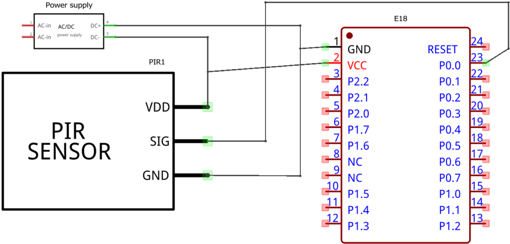
Schematic
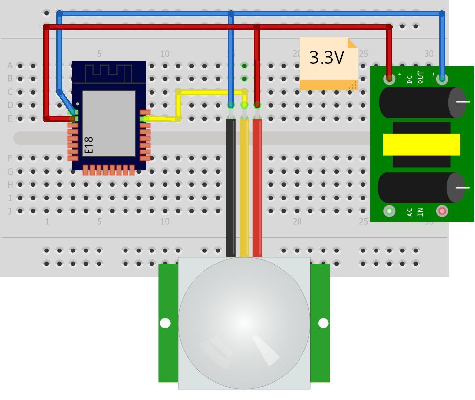
Breadboard
Firmware configuration
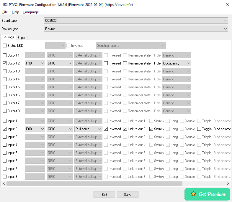
Please note the board type. You should select your variant here:
CC2530 – select it for simple E18.
CC2530+RFX2401 – for E18-MS1PA2, E18-MS1PA2-IPX, E18-2G4Z27SI, or E18-TBH-27.
How it works
The sensor detects movements and raises a signal on the “OUT” line to the high state (3.3V). The firmware interprets this signal level as a pressed button. Because the sensor can hold the high state for a long time, the “switch” mode is selected. The firmware links an input to a virtual output on a virtual (non-existent) pin (CC2530 virtual pins: P30 – P37). It allows you to get the ON (move) and OFF (no movements) states in a home automation system.
You can use any unused pins in this application.
Vic
Hello!
I can see the CC2530 in Hassio with ZHA, but the PIR sensor keeps detecting and not detecting every 2 seconds (I’m covering the sensor to prevent detection). I’ve tried a new PIR and another CC2530, but the same thing happens. I also switched from ZHA to Zigbee2MQTT, added a 10Kohm resistor between P00 and GND, and still the same problem… I don’t know what else to do. Best regards!
Owner
Does the sensor detect movement without real movements?
Vic
Yes, super strange. making continius detections every 2 seconds aprox. I don’t know what to do 🙁
Thom
Hi! I built this circuit, for a battery its energy consumption is extremely high. Would choosing the premium version (set Device type = PSM) be enough to reduce energy consumption? Or is it necessary to change the circuit or other settings? Thanks.
Owner
I think, this sensor was not designed for battery-powered devices. You can try to find a datasheet for it and check the average current.
Thom
Hi.My question was more directed towards the CC2530. It also consumes a lot of current. I checked that the sensor has battery-powered mode.
Owner
Sure, the PSM version will improve power consumption because CC2530 sleeps all the time, and wake-up only when GPIO input changes.
Other versions are always active.
Anxo
Hi! I’d like to build a similar project to this one, adding a relay to turn on a light when the sensor gets triggered. But I’d also like to ignore the sensor during the day.
I know I can have the input and output detached, and have the controller decide when to trigger the output, but it would be great if I could link it directly, just having a virtual “inhibitor switch” that I can turn on/off from the controller. Is this posible?
nakaconsan
Hi, I’ve downloaded the firmware configuration gui, but it saves as ini. How can the setting convert to bin when using objcopy.exe from hex? sorry for such an elementary question and looking forward to your reply. Thanks!
Owner
The program should save HEX when you click the “Save” button.
nakaconsan
Got it. just realised two saves are different. Really appreciated your help.
TL
Is P00 GPIO connected to +3.3V via a 4700 Ohm resistor?
Owner
You do not need this resistor. The firmware uses the internal pull-down resistor.