Owner
Owner Owner
OwnerThis output type allows you to control a state of selected and configured outputs. When you change the “Group switch” state, it reflects on all grouped outputs. So, you can control several outputs by one command.
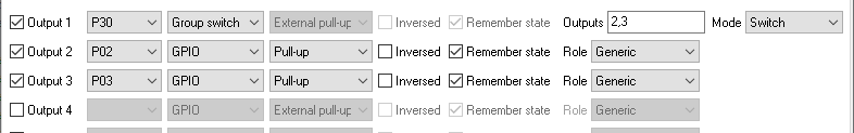
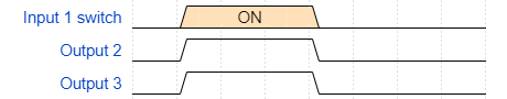
The configuration above allows you to control Output 2 and 3 using one switch connected to Input 1.
The firmware does not control the state of a pin assigned to Output 1 (P01 in this example). You can use any unused pin for the group switch.
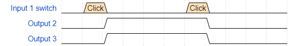
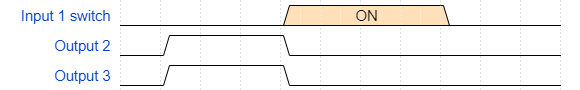
If you disable the “Switch” option for Input1, the waveform diagram will look like this:
Limit switch
In the “Limit switch” mode, you can send any signal to the “Group switch” output, and the firmware switches off all grouped outputs. It is useful to link this output with an alarm input (for example, a water leak sensor).
Interlock mode
The “Interlock” feature prevents two or more GPIO outputs from being active at the same time. The group switch with the “Interlock” mode allows you to define “interlocking group” with a list of all the switches in the group. If one of the switches in the group changes state to “ON,” the firmware sets all other switches to OFF.
The firmware allows setting all switches to the OFF state.
You can send the OFF command on the endpoint with the group switch to change the state of all switches in the group to “OFF.”
Inverted interlock mode
If one of the switches in the group changes state to “OFF,” the firmware sets all other switches to ON.
⚠ Warning ⚠
It is a software interlock, and a software bug can still activate both switches simultaneously. Similarly, at reset time (before firmware code runs), the relay GPIO pins may have pull-ups active, so the relay may be active before the firmware initializes them.
So, it is highly recommended to use hardware interlocks (like SPDT-type relays) to ensure that two GPIOs are never active simultaneously.
Value equal, great/less, in range
⚠️ THIS FEATURE IS AVAILABLE ON CC2652 or CC1352 CHIPS ONLY
These modes allow you to change the output state depending on a value of a controllable output.
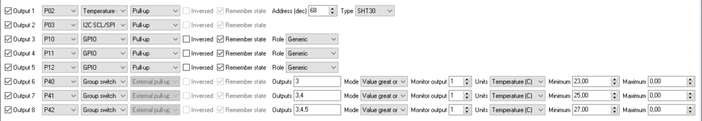
The below configuration example monitors the temperature value from the sensor on Output 1 and sets Output 3-5 depending on the measured value. The outputs can be connected to colored LEDs, which will display the temperature level. This logic is implemented locally, and it will work if a device is temporarily offline.
The minimum and maximum numbers must be between -3276.0 and +3276.0.
If a condition only has one limit, it should be set in the “Minimum” field.