 Owner
Owner Owner
OwnerA rotary encoder is a type of position sensor used to determine the angular position of a rotating shaft. It generates an electrical signal, either analog or digital, according to the rotational movement (more info).
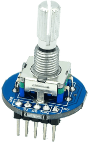
The firmware counts impulses in the 500 ms interval and sends a positive value for CW rotations and a negative value for CCW rotations. Optionally, the firmware can handle and send an event for a click button.
Wiring
Output 2 → S1
Output 3 → S2
Input 1 → Key
GND → GND
3.3V → VCC
Firmware configuration
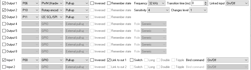
The image above is an example. You can connect “Output 1” and “Output 2” signals to any available pins. The “I2C SCL” line should be defined immediately after the “Rotary encoder” sensor.
Note: Output and input pins are not relevant for sensors. You can also configure your rotary in input pins, but without additional options.
Changes level – this option allows you to link the rotary encoder to a PWM or LED output and control PWM signal width or brightness level up or down.
Sensitivity – this option is used when with the previous option and changes a step size per each tick.
If your encoder has the additional push button, you can connect it to an input, and it will toggle a linked output state.
Jaak
Hello, can I use PTVO board as a replacement for “digital rotary encoder” so I can send CW or CCW commands thru Home Assistant MQTT? Digital encoder main pin is “GND”, so the impulses should be GND
Owner
Hello,
Sorry, but it works in the opposite direction. The firmware interprets signals from a rotary encoder and sends to HA.
alain
I’ve understand the “brightness_l6” : it’s relevant to LED output – the value changes up or down with the encoder rotation CW or CCW
but i don’t have the -1 or 1
Owner
You can unlink the rotary encoder from the output and you’ll get increment and decrement.