 Owner
Owner Owner
OwnerWhen building your own DIY Zigbee devices, incorporating a display can significantly enhance their functionality and user experience. From simple 7-segment LED indicators to more advanced LCD or OLED screens, displays provide a practical and visually appealing way to interact with your Zigbee device. This article will explore the various types of displays you can use, their compatibility with Zigbee-based projects, and tips for integrating them seamlessly into your DIY designs.
⚠️ THIS FEATURE IS AVAILABLE ON CC2652 or CC1352 CHIPS ONLY
General information
The firmware can operate with display that require up to 3 wires to connect. Typically, it is the data and clock pins, like in the I2C interface.
If a display works with characters (e.g., TM163X or LCD1602), all coordinates and dimensions should be specified in characters.
If a display operates with pixels (e.g., SSD1306), all coordinates and dimensions should be specified in pixels.
X and Y coordinates start with 1.
Please consider using a comma as a delimiter for all coordinates and dimensions in the settings.
Connection
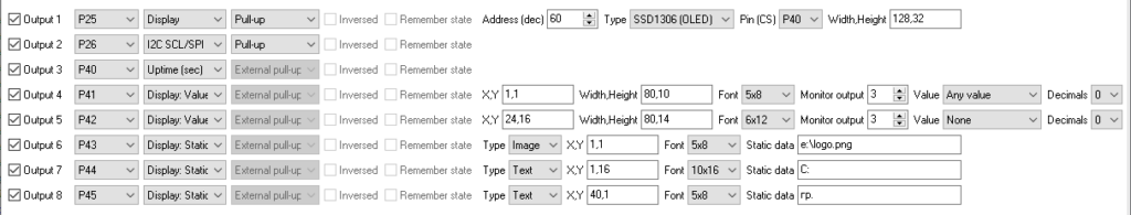
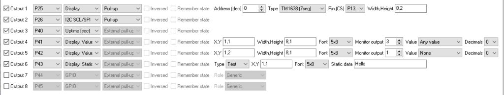
First, define the “Data / SDA” pin for your display (Output 1 in the example below). Immediately after it, define the “SCL / Clock” pin. Select the appropriate pull resistor type. Usually, it is the internal pull-up resistor.
Display settings
Address (dec.) – the decimal address for I2C-compatible displays.
Type – the display type.
Pin (CS) – the additional “chip-select” pin. It can also be marked as a strobe (STB) pin in some displays. If it is not required in your setup, you can select any virtual pin in the field.
Width, Height – comma-delimited display dimensions (in characters or pixels).
Display value settings
This definition allocates an area on your display that can output a value from a sensor connected to your device or from your home automation system.
X, Y – the top-left coordinate of the first character or pixel.
Width, Height – width and height of the area used for the value on your display. If your value is longed than the allocated area, it will be truncated.
Font (for pixel display only) -the built-in font used for the configured value. Really, the firmware includes only two fonts (5×8 and 6×12). The other font sizes are the result of the scaling of existing fonts.
Monitor output – the output number with the connected sensor that can publish a value in the display area. If you would rather not display any value from an onboard sensor, select any non-existent output here.
Value – If your sensor measures and sends several values to a coordinator, the value is the unit of the sensor’s value. Select “None” if you would rather not display any linked values. Select “Any value” if your sensor only measures one value, or you don’t know the units of it.
The firmware outputs a new value from a sensor when it sends a new periodic report. If a period report interval is 20 seconds, the linked value on a display will be updated once every 20 seconds.
Decimals – the number of digits after a decimal point of displayable value.
You can add multiple display values in the configuration.
Display static element settings
Static elements are used to output a static text or graphics once on boot. For example, you can prepend your value with a description or add units to it.
For graphics displays you can add and output a background image with your logo, for examples.
Type – the element subtype: Text – static text, Image – static background image.
X, Y, Font – the same settings as for a value.
Static data is text (up to 5 Latin characters or numbers) or a static image file name. Please note, that the program cannot read the image content of the existing firmware HEX file.
You can add multiple static elements in the configuration.
TM1637 and TM1638 based 7-segment displays
TM1637 and TM1638-based 7-segment displays are popular choices for projects that require clear numeric or alphanumeric output in a compact form. These integrated driver ICs simplify the process of controlling 7-segment displays.
This controller type supports up to eight 7-segment indicators in a row.

The additional row of LED indicators is supported by the “TM1638” controller. You can access them by defining the second row in the settings. In the example below, output 5 contains a definition for the second row with single LEDs. Write a space or 0 character at the necessary position to turn off the LED, and any other character to turn it on.
HD44780 (or a compatible) LCD via I2C
⚠️ THIS FEATURE REQUIRES THE PREMIUM VERSION
The HD44780 LCD, or its compatible variants, remains a go-to choice for displaying text in countless electronics projects. When paired with an I2C interface, this versatile display becomes even easier to integrate, requiring fewer pins and enabling seamless communication with microcontrollers.
The firmware supports LCD screens with various popular dimensions: 1602, 1604, 2004.
Note: the most LCDs work with 5V only. You’ll need a level shifter to connect it to an MCU.
Here is a guide on how to use LCD1602 with 3.3V and get the correct contrast for displayable characters.

SSD1306 OLED display
⚠️ THIS FEATURE REQUIRES THE PREMIUM VERSION
The SSD1306 OLED display, available in 128×32 and 128×64 resolutions, is an excellent option for projects requiring crisp, high-contrast visual output. These compact displays are ideal for presenting text, simple graphics. With their support for the I2C interface, they provide flexibility in connectivity while consuming minimal power.
Currently, the firmware supports only two popular dimensions of OLED displays: 128×32 and 128×64.
How to send a value from your home automation system
The firmware accepts “attribute – write” commands through the standard “Analog Input” cluster.
Zigbee cluster: ZCL_CLUSTER_ID_GEN_ANALOG_INPUT_BASIC
Zigbee attributes:
| Attribute | Attribute ID | Description | Data type | Data type code |
|---|---|---|---|---|
| 0x0001 | ATTRID_IOV_BASIC_PRESENT_VALUE | Numerical value | Single precision float | 0x55 |
| 0x001C | ATTRID_IOV_BASIC_DESCRIPTION | Free text | Char string up to 254 characters | 0x42 |
Zigbee2MQTT commands
write – immediately reads the analog input value
write - Zigbee write command.
Topic: zigbee2mqtt/[friedly_name]/set
Payload: {"[channel]": 1234.567}
Channel: l1, l2, l3 … l16
Zigbee2MQTT cannot directly send a text value. But you can create and add a custom external converter for your device.
Thomas Lentz
Hi,
is it possible to use a display periodically and power it down in between?
This would be really useful for battery-powered sensors.
Do you plan to support an ePaper-display like the 1.9″ waveshare e-Paper?
https://www.waveshare.com/wiki/1.9inch_Segment_e-Paper_Module_Manual#Overview
Greetings
Tom
Owner
You can configure and connect any GPIO output to control the brightness or common cathode of an indication. Then you can switch it on/off remotely.
The ePaper indicator looks great, but it is expensive for testing :). Furthermore, it is rather unpopular.